| Line 338: | Line 338: | ||
===Adjustable Pipe System=== | ===Adjustable Pipe System=== | ||
Firstly, the underwater rope guide is to be set up. Figure | |||
=='''Cost Estimation'''== | =='''Cost Estimation'''== | ||
Revision as of 17:34, 15 April 2010
Abstract
Background
|
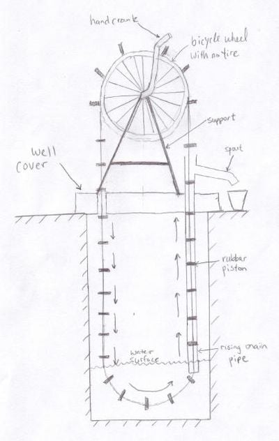
Figure 1 - A basic rope pump schematic
History
Rope pumps were first developed as a relatively inexpensive solution for drawing water out of wells up to 50 metres deep. Within the 1970's and 80's, specifically in Nicaragua, many different rope pump designs began to emerge - specifically the one shown in figure 1 above. Once the foundation for this technology was discovered, the 1980's proved to be a major optimization period for the new technology. Quite possibly, the most significant development in the 80's was the ability to inject plastics into moldings, leading to the use of inexpensive PVC pipes. Not only being inexpensive, the durable, long lasting and rust-preventative nature of polyvinyl-chloride has led to its continual use in rope pumps in this present day.
The Standard Rope Pump
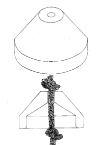
Figure 1 shows a simple diagram of how the standard rope pump developed in the 1980's works. Above the hand-dug well is a bicycle wheel without its tire (the inner rings of a used car tire clamped together can also be used), which is able to freely rotate about its axis. Connected via chain to the bicycle wheel is another pinion, which contains the pedals (or hand crank) used to turn the wheel. Different sizes of pinions can be used to further limit the load needed, however, with a reduction of load comes a reduction of speed and thus mass flow rate. A rope runs along the edge of the bicycle wheel and dips freely into the well, finally running up a fixed PVC pipe (which runs down just below the surface of the water) and back to the bicycle wheel. Attached to this rope at fixed distances apart are "pistons" which have are just smaller than the PVC pipe diameter. Figure 2 illustrates these pistons.
|
Figure 2 - Rope pump piston
The tolerance of the pistons are key, noting that a smaller tolerance will lead to a major reduction in efficiency, while a larger tolerance will effectively lead the piston diameter to be as large (or larger) than the pipe diameter, causing the device to become "stuck."
As the bicycle wheel is turned, the rope and pistons move freely downward, before dipping just under the water surface. The pistons then get pulled into the PVC pipe, and create a suction with the surrounding walls. Upon immediate entrance of the pipe, any water above the piston will begin to be pulled upward. Finally, a spill pipe above the well surface allows water being pulled up to be collected for use. The cycle then repeats itself, as each piston travels along the bicycle wheel, and down into the well once again.
Drawbacks of the Standard Rope Pump
Although very effective in developing countries, the rope pump still contains many drawbacks, from versatility to user friendliness. Some of these drawbacks include depth limitations, material considerations for separate depths, and the "average" force settled for to move the wheel (i.e. children should be able to pump, meaning that an adult will not be using their maximum amount of force to pump). Table 1 illustrates the suggested diameter tubing for certain water depth levels.
Table 1
| Elevation | Diameter (inner) | Diameter |
| 0 - 4 meter | 40 mm | 1.5 inch |
| 4 - 11 meter | 30 mm | 1 inch |
| 11 - 20 meter | 23 mm | 0.75 inch |
| 20 - 60 meter | 18 mm | 0.5 inch |
Due to the lack of tools and supplies, the well depth often cannot be estimated properly. Currently, one of the most accurate ways to measure the depth of a well is as follows:
- Tie a relatively heavy object to the end of a long rope, and lower the rope until it touches the surface of the water
- Tie a knot once the surface of the water is contacted
- Continue lowering the rope until the bottom of the well is touched
- Tie another knot in the rope
- The distance from one knot to the other is the approximate depth of the well
An improper estimation of the well depth can lead to the implementation of an incorrect PVC pipe. If the diameter of the pipe used is too big, too much water may be collected at once. This amount of water may become to heavy to be brought to the surface, rendering the system useless.
The Depth-Adjustable Rope Pump
This type of pump uses an adjustable PVC piping system to vary both the depth of the system, and the force needed to bring up water. The pipe is able to be lowered to a desirable depth, and locked in place, so that it remains rigid while in operation. If the pipe is dropped down too low, or the force of pumping becomes to heavy for a child, it may be slowly raised up via the bicycle wheel and a second rope. With this new design, the suggested diameter tubing is shown in Table 2.
Table 2
| Elevation | Diameter (inner) | Diameter |
| 0 - 60 meters | 30 mm | 1 inch |
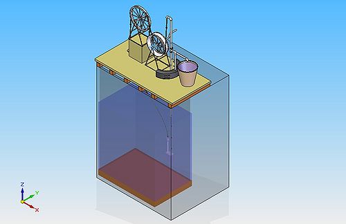
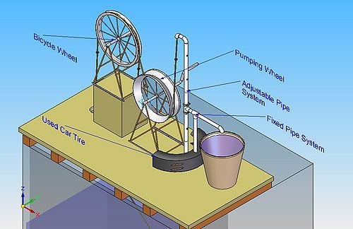
The full design is shown in figures 3, 4, 5 and 6, and is constructed step-by-step in sections below.
 |
 |
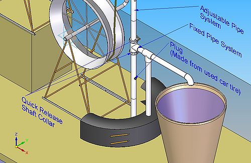 |
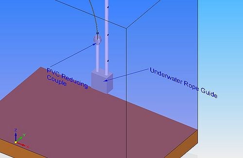 |
Design Components
Pumping Wheel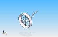 |
The pumping wheel is composed of two inner rings of used car tires, clamped together and held in place by spokes. Once these two rings are clamped together, the 'v' type shape provides enough friction to move the rope, and effectively bring water up the pipe. The exact construction process can be found within the 'How to Make' section of http://www.ropepumps.org. The handle is made from 1" steel pipe, bent into two separate 90-degree angles. |
Well Cover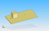 |
The well cover is a platform made from a piece(s) of plywood or even particle board, serving multiple purposes. Firstly, covering the well surface prevents contamination, which can compromise the quality of the water, and cause the pump to become 'stuck' (this can happen if large pieces of debris enter the pipe and become lodged). Secondly, it is a platform for many of the rope pump components to rest or be fixed to. |
Used Car Tire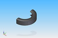 |
This used car tire (found from collecting inner rings to make the pumping wheel) is used as a rigid support, being secured by nails to the well covering, and in turn, holding many piping systems in place through the use of concrete rebar. |
Rope with Pistons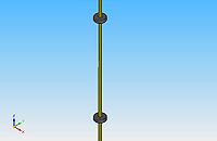 |
The rope runs throughout the entire system, having pistons situated at 1-meter intervals along its length. These pistons can be fashioned out of used car tires, as circles are cut to be precisely the same diameter as the pipe they are to travel through (in this case, 1"). The edges of these circles can then be slightly trimmed, so that they fit through the pipe, but still create a large enough suction to efficiently bring water up. |
1" PVC pipe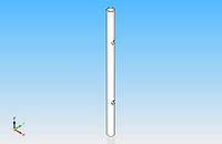 |
Several lengths of PVC tubing is used throughout the system. The model shown here has two holes drilled at 125 mm apart, allowing water brought up from the well to exit. |
1" PVC Elbow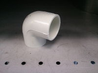 |
The PVC elbow fitting is commonly used throughout the piping system extending down towards the bottom of the well. |
1"/2" PVC T-joint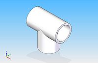 |
The PVC t-joint fitting is commonly used throughout the piping system extending down towards the bottom of the well. |
Bicycle Rim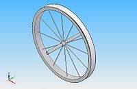 |
In order to keep tension around the pumping wheel, another fixed point is needed. The bicycle rim serves as this point, as it keeps tension in the rope and directs it down into the well. |
Concrete Rebar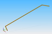 |
This material is used as both a 'lever' for the adjusting collar (see next item), and a restraining piece, holding parts of the piping system to the used car tire. |
Adjusting Collar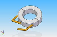 |
The adjusting collar is used to either lower the pipe system (when unlocked) or hold it rigidly in place (when locked). The piece is a product of misumiusa.com, and can be found at http://www.misumi-ec.com/usa/eusaen/ItemDetail/10302155240.html. In order to allow the unit to be quickly release and tightened, without the constant use of a hex-key, small lengths of commonly found concrete rebar are welded to the head of the bolt. The rebar can then be bent to resemble that of a handle. |
Wheel Structure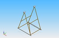 |
Made from pieces of 1-1/4" metal tubing, rebar and two L-shaped brackets all welded together, the wheel structure is responsible for supporting the pumping wheel, and allowing it to freely rotate. |
Underwater Rope Guide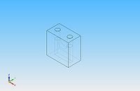 |
This guide is situated underwater, allowing the rope and pistons to smoothly transition from being lowered into the well to rising back up again. The guide can be a block of wood, with a semi-circular (approximately) cut through the bottom, and two 2" holes (again, approximately) cut on each side of the semicircle. |
2"/1" PVC Reducing Couple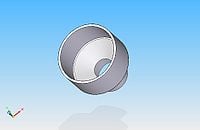 |
The PVC reducing couple fitting is used to accurately guide the rope and pistons into the underwater rope guide, without the pistons getting caught on the side of the pipe. |
Engineering Calculations and Principles
For the following calculations, parameters are represented by the following:
- h - pipe extension distance below the water surface (m)
- Lw - length of tubing from surface of the water to water spout (m)
- Lpvc - total length of adjustable PVC pipe in the system (m)
- ρw - density of water (kg/m3)
- ρpvc - density of PVC (kg/m3)
- g - acceleration due to gravity (m/s2)
- Awater - cross-sectional area of water in the pipe (m2)
- Apvc - cross-sectional area of the PVC pipe (m2)
- μ - coefficient of friction between plastic and nylon
- ID - inner diameter of PVC tubing (m)
- OD - outer diameter of PVC tubing (m)
- rcrank - radius of crank handle (m)
- rpumpwheel - radius of the pump wheel (m)
- H - total height of water in the system (m)
- mw - mass of water in the system (kg)
- mc - mass needed to rotate crank (kg)
- Ff - force due to friction (N)
- Fw - force of water in the system (N)
- Fc - force needed to rotate crank (N)
Pumping Calculations
The spreadsheet File:Crank forces.xls can be used to determine a variety of required crank forces for different lengths of PVC pipe and below-surface depths. The separate tabs within the excel file represent different depths the pipe extends beneath the surface of the water (d). All the values within the spreadsheet are based on the following calculations.
The system can be simplified in order to accurately make calculations relevant to the user. Figure 7 shows where the load of the pulley system is situated.
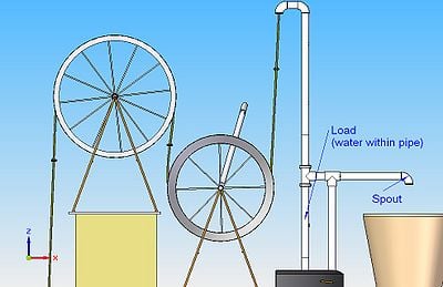 |
Figure 7 - Load in the pulley problem
In order to calculate exactly how 'hard' a user is to rotate the crank to bring a specified amount of water up, the system shown in figure 7 can now be modeled as in figure 8.
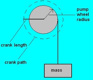 |
Figure 8 - Simplified pulley system
Where the mass represents the total weight of the water being pumped upwards. However, it can also be noticed that in figure 7, the rope passes through two elbow sections, and changes direction before it passes the pump wheel. Because of this, the frictional force of the rope along this length of elbow sections will also have to be considered in the calculation.
Therefore, 'mw' now represents the total mass of water being pumped upward in the pipe. The force of the water, Fw, can then be found.
Not only does the water traveling up the pipe create a force on the pump crank, but the transition piece shown in figure 9 presents an added resistance as well. As the rope travels to the very top of the pipe, it turns a gradual 90-degrees, following the path of the connected elbow. Because the rope is almost instantaneously brought back through another elbow and fed downwards, the rope will tend to slide along the horizontal portion of the pipe. The problem at hand can then be modeled using the scenario in figure 10.
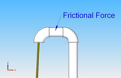 |
Figure 9 - Friction in the pipe
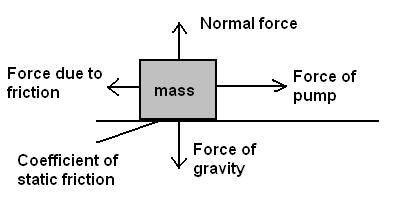 |
Figure 10 - Simplified forces on the rope through the horizontal section
The coefficient of dynamic friction of PVC on steel is quoted as 0.25. However, steel, with a dynamic coefficient of 0.8, is much higher than that of nylon (0.2). Therefore, a lower coefficient of friction of approximately 0.1 is used for nylon on PVC. Therefore, the force due to friction can be calculated by using the coefficient of friction as the ratio of forces.
The total force on the pump crank can then be calculated by simply adding the force due to friction with the force of the water rising in the pipe. The force felt by the user rotating the crank can then be computed by referring to figure 8. The forces of each the water and the crank are proportional to their respective lengths.
Lifting Calculations
Being a depth-adjustable pump, sometimes the piping system will need to be lifted if the force of pumping is greater than the user can handle. The simple method of draining the PVC pipe before lifting is explained in the Technical Details section. After the pipe is completely drained, the mass being lifted upward is made up of the adjustable section of PVC piping, along with its fittings (the mass of the underwater rope guide can be neglected due to the small nature of its size). The mass of the adjustable PVC pipe in the system can be
Based on the previous calculations, figure 11 shows the length of adjustable PVC tubing within the system, and its corresponding weight when lifting. It is important to keep in mind that part of this tubing may be submerged, which would make the system easier to lift upwards.
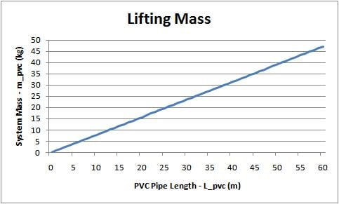
Figure 11 - Lengths of PVC tubing and their corresponding masses
Required Materials and Tools
Much of the major required materials are outlined in the design components section and are readily available locally. However, there are other small materials and tools needed in order to fully construct the pump and make it operable. Simple tools such as hammers and hand-drills should be readily available in order to open parts of the well cover to the well surface, as well as to fix certain components permanently to the well cover.
Small-scale materials
Some smaller materials needed to construct the pump are outlined.
- PVC cement is needed to connect piping. A guide to PVC gluing can be found at http://www.hammerzone.com/archives/plumbing/technique/pvc/gluing/joining_pipe.htm. As an alternative to glue, the pipes can be connected and the outside can be heated to its melting point, where the two joints will fuse.
- Any range from 10d to 60d box nails - information on sizing can be found at http://www.sizes.com/tools/nails_smooth_box.htm.
- Wooden beams - at least 2in x 4in - used as a support for the well cover. See http://www.ropepump.com/images/InstallationManual.pdf Specifications of the well covers and structures to fasten the rope pump.
Required Tools
- hammer
- hand drill
- panel saw
- stick welder - DOY ideas can be found at http://www.instructables.com/id/Weld/
Required Skills
The construction of the adjustable rope pump should be, at the very least, overseen by any person with experience in building and welding. When constructing either the original rope pump or the adjustable rope pump, relatively large-scale construction is being performed over a very hazardous surface. It is recommended that the system is constructed in groups, so that supervision is present at all times of construction.
Proper construction of the original rope pump can be found at http://www.ropepump.com/images/InstallationManual.pdf.
Construction
- The construction of the main support well cover can be found at http://www.ropepump.com/images/InstallationManual.pdf
Fixing components to the well cover
Figure 12 shows the cut-outs on the well cover and tire. Note that the holes in the well cover do not need to be exact, just ensure that there is enough space for the pistons along the rope to move through.
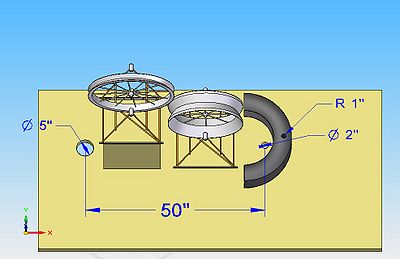 |
Figure 12 - Dimensions on well cover drills
Figure 13 shows the orientation of each structure. Note that the bicycle wheel frame and the pump wheel frame should be positioned so that the edge of the bicycle wheel is approximately vertically in-line with the edge of the pumping wheel.
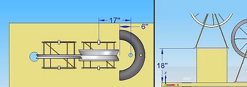 |
Figure 13 - Fixed component distances
The three components can then be fixed with the required box nails outlined in the Required Materials section.
Fixing the wheels
Figure 14 shows the welding point at which the pumping wheel is welded to its 1" steel pipe. The long steel pipe can then be bent into two separate 90-degree bends, creating a handle. The bend is shown in figure 15. It should also be noted that the vertical length of the handle will determine how easy it is to pump. In the calculations done in File:Crank forces.xls, the handle extends approximately 160% of the wheel diameter.
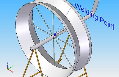 |
Figure 14 - Weld point
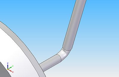 |
Figure 15 - This type of bend can be done with a hammer
Fixed Pipe System
Note: the fitting of PVC can be found in the link provided in the Required Materials section.
Figure 16 shows the setup of the fixed pipe system - the section of piping that will remain stationary at all times. This system is made up of 2" PVC piping and fittings. Within figure 16, the t-joint T1 should be axial aligned with the hole in the well cover within the tire, while T2 should be axial aligned with the hole in the tire. The other part of figure 16 shows how rebar is used to secure the piping to the tire. These holes for the rebar can be made using a hand drill. The ends of the rebar are bent to the circumference of the tire, to ensure there is no movement.
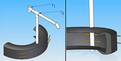 |
Figure 16 - The fixed pipe system
Adjustable Pipe System
Firstly, the underwater rope guide is to be set up. Figure


