*There are 36 sheet metal screws attaching the apex ends (motor and idler) to the linking boards and base plates. Hand tightening all of these screws can be tiring, especially as a stubby screwdriver is required for many of the screws. An angled (90 degree) electric driver can greatly ease this task and is recommended.
*There are 30 sheet metal screws attaching the apex ends (motor and idler) to the linking boards and base plates. Hand tightening all of these screws can be tiring, especially as a stubby screwdriver is required for many of the screws. An angled (90 degree) electric driver can greatly ease this task and is recommended.
*If the tie rod ends have been assembled and the epoxy has set, disassemble the tie rod jig as the end pieces serve as drill hole guides for the linking boards.
*If the tie rod ends have been assembled and the epoxy has set, disassemble the tie rod jig as the end pieces serve as drill hole guides for the linking boards.
*If your linking boards have any kind of design ensure that the orientation is correct - the tabs with holes are at the top to hold the platform.
*If your linking boards have any kind of design ensure that the orientation is correct - the tabs with holes are at the top to hold the platform.
Line 20:
Line 20:
# [[File:MOST_Delta_025.JPG|thumb|right|Positioning base plate under motor end assembly.]]Lay the motor end assembly on top of one of the round pieces of plywood with the flanges down and carefully position it such that the assembly is centered on the circle. Mark the locations of the base plate mounting screws with a sharp pencil or other sharp object taking care to not move the two pieces relative to each other. (Clamping or starting a pair of screws can keep the two pieces from moving relative to each other.)
# [[File:MOST_Delta_025.JPG|thumb|right|Positioning base plate under motor end assembly.]]Lay the motor end assembly on top of one of the round pieces of plywood with the flanges down and carefully position it such that the assembly is centered on the circle. Mark the locations of the base plate mounting screws with a sharp pencil or other sharp object taking care to not move the two pieces relative to each other. (Clamping or starting a pair of screws can keep the two pieces from moving relative to each other.)
# Mark the relative location of the motor end assembly to the base plate by drawing a line through the center of one of the linking boards and a matching line on the round plywood piece. Mark the round plywood piece to indicate it's for the bottom (“B”).{{clear}}
# Mark the relative location of the motor end assembly to the base plate by drawing a line through the center of one of the linking boards and a matching line on the round plywood piece. Mark the round plywood piece to indicate it's for the bottom (“B”).{{clear}}
#There are two styles of pulleys - one with a round shaft opening and one with a "D" profile shaft opening. DO NOT ream the "D" shaft opening with 5mm drill bit - it is designed to be a snug fit and may require some force to push onto the motor shaft. Use a 3mm drill to ream the set screw holes. If necessary, use a sharp knife to remove flashing from the nut traps for the set screw. Clean off any protrusions from the cogged portion of the pulleys.
# [[File:MOST_Delta_026.JPG|thumb|right|Assembled pulley.]]Insert M3 nuts into the nut traps in the pulleys, push them all the way to the bottom of the trap using a small screw driver if necessary.
# Start the M3 x 8mm set screws into the nuts in the pulleys. Do not allow them to extend into the 5mm hole for the motor shaft.{{clear}}
# [[File:MOST_Delta_027.JPG|thumb|right|Motors with pulleys.]]Place the motors on the table such that their shafts face upward. Push pulleys, set screws down, onto the motor shafts making sure to align one of the set screws with the flat on the motor's shaft. Push the pulley all the way on the shaft until the gap between the pulley and motor housing is a millimeter or less. Remove the set screws and apply a small amount of thread locking compound and return them to the pulley. Thoroughly tighten the set screws.{{clear}}
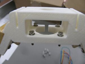
# [[File:MOST_Delta_028.JPG|thumb|right|Motor end with screws.]]Prepare 12 M3 x 14mm socket head cap screws each with an M3 washer. Stand the motor end assembly up on one linking board such that a motor end is facing upward. Carefully drop a screw with its washer into the motor mount holes.
# [[File:MOST_Delta_028.JPG|thumb|right|Motor end with screws.]]Prepare 12 M3 x 14mm socket head cap screws each with an M3 washer. Stand the motor end assembly up on one linking board such that a motor end is facing upward. Carefully drop a screw with its washer into the motor mount holes.
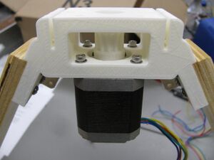
# [[File:MOST_Delta_029.JPG|thumb|right|Motor end with motor.]]Position the motor with the pulley facing up and the wires to your right and start the M3 x 14mm screws into the motor. Do not tighten any of the screws until all four are started in the motor. Once all four screws have been started, tighten them, securing the motor end to the motor.{{clear}}
# [[File:MOST_Delta_029.JPG|thumb|right|Motor end with motor.]]Position the motor with the pulley facing up and the wires to your right and start the M3 x 14mm screws into the motor. Do not tighten any of the screws until all four are started in the motor. Once all four screws have been started, tighten them, securing the motor end to the motor.{{clear}}
There are 30 sheet metal screws attaching the apex ends (motor and idler) to the linking boards and base plates. Hand tightening all of these screws can be tiring, especially as a stubby screwdriver is required for many of the screws. An angled (90 degree) electric driver can greatly ease this task and is recommended.
If the tie rod ends have been assembled and the epoxy has set, disassemble the tie rod jig as the end pieces serve as drill hole guides for the linking boards.
If your linking boards have any kind of design ensure that the orientation is correct - the tabs with holes are at the top to hold the platform.
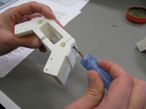
Cleaning motor end.Clean the motor end by reaming out the motor mount holes with a 3mm drill and/or an M3 threaded rod. Ream the clamp screw holes with a 3mm drill. Remove any protrusions or flashing from the linking board mount tab with a sharp knife. The knife can be used as a scraper to remove irregularities on the tab face.
If linking boards (240mm x 42mm x 12mm) do not have pilot holes drilled in them, first mark one long edge as the bottom then use the supplied templates to mark the position of the pilot holes. Note that the templates have a recess that the bottom corners of the boards must fully butt-up against for the hole locations to be correct. Drill pilot holes with a 1.5mm (1/16”) drill bit. Do not drill all the way through the board.
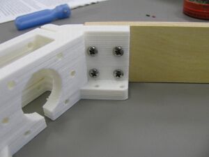
Linking board attached to motor end.With the motor end laying on the table, flanges down, position a linking board so that the pilot holes align with the holes in one of the tabs. The board and motor end must be flat against the table and the board must be firmly against the stop on the motor end. Start four #6 x 3/4” sheet metal screws into the tab but do not start them into the linking board until the position of the board is checked – the board must be firmly against the stop on the motor mount. Once in position, tighten the screws. (Two screws per tab are probably sufficient, but maximum rigidity and longer maintenance intervals can be assured by using all four screws in each tab.)
Repeat with another linking board on the other side of the motor end. A stubby screwdriver will be required to engage some of the screws.
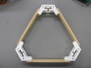
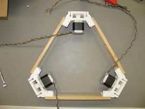
Motor ends and linking boards assembled.Continue with remaining linking board and other two motor ends. When complete, the motor ends should form the apexes of an equilateral triangle and the whole assembly should lie flat on the table top, flanges down.
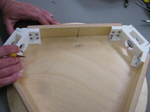
Positioning base plate under motor end assembly.Lay the motor end assembly on top of one of the round pieces of plywood with the flanges down and carefully position it such that the assembly is centered on the circle. Mark the locations of the base plate mounting screws with a sharp pencil or other sharp object taking care to not move the two pieces relative to each other. (Clamping or starting a pair of screws can keep the two pieces from moving relative to each other.)
Mark the relative location of the motor end assembly to the base plate by drawing a line through the center of one of the linking boards and a matching line on the round plywood piece. Mark the round plywood piece to indicate it's for the bottom (“B”).
Motor end with screws.Prepare 12 M3 x 14mm socket head cap screws each with an M3 washer. Stand the motor end assembly up on one linking board such that a motor end is facing upward. Carefully drop a screw with its washer into the motor mount holes.
Motor end with motor.Position the motor with the pulley facing up and the wires to your right and start the M3 x 14mm screws into the motor. Do not tighten any of the screws until all four are started in the motor. Once all four screws have been started, tighten them, securing the motor end to the motor.
Rotate the motor end assembly and repeat with the remaining two motors.
Check that an M3 nut will thread onto the threaded rods from both ends. Check each threaded rod before proceeding.
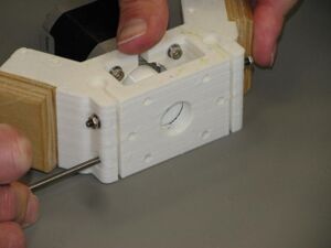
Motor end with guide rod clamping screws.Place an M3 washer and nut onto one of the 85mm long M3 threaded rods. With the motor end assembly flat on the table, push the threaded rod through one of the motor end guide rod clamps. Place an M3 washer and nut on the opposite end of the threaded rod. Do not tighten the nuts. Repeat with the remaining clamp and proceed to the next remaining motor ends doing likewise.
Nearly completed motor end assembly.Braid the motor wires.
If necessary, drill an 8mm (5/16”) hole in a linking board near a motor, thoroughly reaming the hole to enlarge it somewhat.
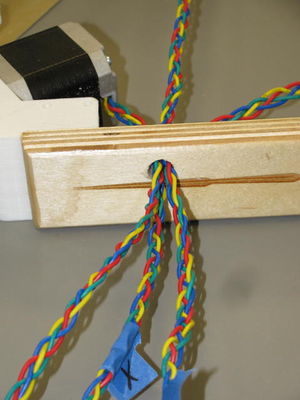
Motor leads passing through 8mm hole in linking board.Thread the braided motor wires through the hole. The fit is tight and care must be taken not to strip insulation of the last set of wires through the hole.
Identify motor wires with their motor by placing a piece of masking tape around the motor wires and on the motor end having the motor the wires are attached to. Mark one set of wires and their associated motor “X” and another “Y”. The third motor/wire set can remain unmarked – it will be motor “Z”.
Place the round plywood that was prepared earlier on the table with the pilot holes up. Place the motor end assembly on the round, aligning the marks on the round with the mark on the linking board. Make sure the pilot holes are aligned with the holes in the motor end flanges and using M3 x 19mm (#6 x 3/4”) sheet metal screws, affix the motor end assembly to the round plywood.