# Drill 2mm pilot holes into the round plywood at the marked locations. Do not drill through the wood.
# Drill 2mm pilot holes into the round plywood at the marked locations. Do not drill through the wood.
# Attach the idler end to the round with #6 x 3/4" sheet metal screws.
# Attach the idler end to the round with #6 x 3/4" sheet metal screws.
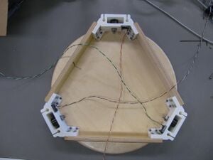
# [[File:MOST_Delta_037.JPG|thumb|right|Complate idler end assembly.]]Place M2 washers on a pair of M2 x 10mm screws. Place one of the [http://www.appropedia.org/Soldering_and_Tinning:MOST assembled limit switches] into the pocket located on the inside face of one of the idler ends. The switch's tab should be positioned so that it is nearest the idler shaft. Affix the limit switch to the idler end with the two M2 screws. Repeat with the remaining two idler ends.
# [[File:MOST_Delta_037.JPG|thumb|right|Complate idler end assembly.]]Place M2 washers on a pair of M2 x 10mm screws. Place one of the [http://www.appropedia.org/Soldering_and_Tinning:MOST assembled limit switches] into the pocket located on the inside face of one of the idler ends. The switch's tab should be positioned so that it is nearest the idler shaft. Mix a small amount of two part plastic epoxy and apply some of it to the limit switch pockets in the idler ends. Affix the limit switches to the idler end with the M2 screws.
# Set the idler end assembly aside.
# Set the idler end assembly aside.
[[File:MOST_Delta_037.JPG|left|Complate idler end assembly.]]
[[File:MOST_Delta_037.JPG|left|Complate idler end assembly.]]
Clean the idler ends with a sharp knife, removing any protrusions from the faces in the interior of the idler box. Use an M8 drill bit or an M3 threaded rod to ream all of the holes. Clear all protrusions from the linking board mount tabs.
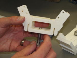
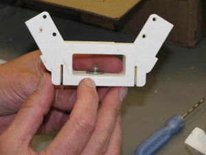
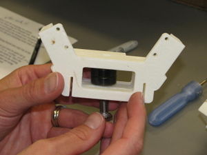
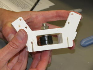
Start the bolt through an idler end.Put a washer on.Put on the bearings.A washer between the bearing and then a washer and nut to secure.The idler is best assembled in steps, inserting a piece, advancing the bolt and then inserting the next piece: Start the M8 x 40mm bolt through the idler end from the side having the hexagonal relief for the bolt head. Push the bolt in only until the bolt just extends into the idler box and then place an M8 washer over the end of the bolt. Advance the bolt a bit more and place one of the 608 bearings on it. Repeat with another 608 bearing and finally an M8 washer. Push the bolt all the way into the hexagonal relief, place a washer and nut on the opposite end and tighten.
Repeat with remaining two idler ends.
The following steps are identical to those performed with the motor end assembly; refer to that page for details and pictures.
If linking boards (240mm x 42mm x 12mm) do not have pilot holes drilled in them, first mark one long edge as the bottom then use the supplied templates to mark the position of the pilot holes and drill them with a 1.5mm (1/16”) drill bit. Do not drill all the way through the board.
With the idler end laying on the table, flanges down, position a linking board so that the pilot holes align with the holes in one of the tabs. The board and idler end must be flat against the table and the board must be firmly against the stop on the idler end. Start four #6 x 3/4” sheet metal screws into the tab and linking board but do not tighten until all of the screws are started and the position of the board is checked – it must be firmly against the stop on the idler mount. Once in position, tighten the screws. (Two screws per tab are probably sufficient, but maximum rigidity and longer maintenance intervals can be assured by using all four screws in each tab.)
Repeat with another linking board on the other side of the idler end.
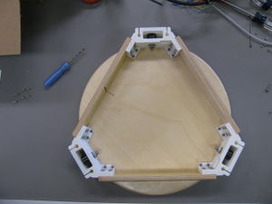
Continue with remaining linking board and other two idler ends. When complete, the idler ends should form the apexes of an equilateral triangle and the whole assembly should lie flat on the table top, flanges down.
Position idler end assembly on base plate.Lay the idler end assembly on top of one of the remaining round piece of plywood, with the flanges down and carefully position it such that the assembly is centered on the circle. With a sharp pencil, mark the locations of all the holes in the plywood round. Remove the idler assembly from the round.
Drill 2mm pilot holes into the round plywood at the marked locations. Do not drill through the wood.
Attach the idler end to the round with #6 x 3/4" sheet metal screws.
Complate idler end assembly.Place M2 washers on a pair of M2 x 10mm screws. Place one of the assembled limit switches into the pocket located on the inside face of one of the idler ends. The switch's tab should be positioned so that it is nearest the idler shaft. Mix a small amount of two part plastic epoxy and apply some of it to the limit switch pockets in the idler ends. Affix the limit switches to the idler end with the M2 screws.