[[File:MOST_Melzi_jumpers_highlight.jpg|thumb|right|Melzi controller board with jumpers highlighted.]]There are two jumpers on the Melzi controller board as shown in the image to the right. The jumper in the middle of the board determines from where the controller will get power, either the USB cable or board power (supplied to power terminals on the Melzi board). Either may be appropriate:
*When set to board power, the controller will only be powered when power is applied to the Melzi's power terminals. This is slightly more stable, so if you experience connection loss, use this setting.
*When set to USB power, the controller will be powered whenever the USB cable is plugged into a powered port, like on a computer.
The jumper on the bottom of the board determines if the controller auto-resets when a connection made to a computer via the USB cable. The jumper should be over both pins when uploading firmware or an error will result.
{{clear}}
{{clear}}
=Melzi Thermistor Fixed Resistor Value=
=Refresher=
[[File:MOST_Melzi_resistor_highlight.jpg|thumb|right|Melzi controller board with locations of fixed resistors highlighted.]]In order to configure firmware so that it controls hot end temperature, both the resistance of the thermistor and the resistance of the fixed resistor on the Melzi board must be known. Note the numbers on the resistors highlighted in the image at right and compare to the magnified images of the resistors:
Remember in the [http://www.appropedia.org/MOST_RepRap_Primer#Firmware RepRap Primer] that firmware is software that runs on the controller. The firmware must be uploaded to the controller before subsequent steps can be performed.
=Note=
*'''Windows operating system''' frequently has a hard time loading the correct Arduino drivers:
# Open the Windows device manager (different for different Windows versions - do a web search to learn how to access it if you are unsure).
# Look for an unknown usb device in the list - it might include something about FTDI in the device description.
# If there is an unknown usb device, install the device driver (in most Windows versions, right click on the device entry and select 'Update driver').
# DO NOT use automatic update - instead, select browse your computer.
# The drivers are typically located in C:\Program Files\Arduino\drivers.
# Depending on the version of Windows, this process may need to be repeated twice as there are actually two separate drivers for this single device (thanks, Microsoft).
*'''Mac OSX''' can have problems with the Arduino driver
# '''Problem 1:''' manifesting "serial port in use" errors when attempting to upload.
# Solution 1A: The driver file is located at [http://www.ftdichip.com/Drivers/VCP.htm].
# Solution 1B: Open a terminal session.
# Run lsof | grep usbserial, which return something like: activhard 257 elmhirstka 4u CHR 19,1 0t15 607 /dev/cu.usbserial-A703B45K.
# Take note of the process id - in the line above, it's the first number in the line (257).
# In the terminal session, run kill (process #). In the example, above: kill 257
# '''Problem 2:''' MacOSX doesn't recognize melzi as a USB device at all.
[[File:MOST_Melzi_4700.jpg|thumb|left|4.7k-ohm resistor.]]If the number is 4700 (4.7 k-ohm), set EXT0_TEMPSENSOR_TYPE to 1.{{clear}}
# Solution: Install the most recent FTDI driver file located at [http://www.ftdichip.com/Drivers/VCP.htm]
[[File:MOST_Melzi_10000.jpg|thumb|left|10k-ohm resistor.]]If the number is 1002 (10 k-ohm), set EXT0_TEMPSENSOR_TYPE to 97, uncomment USE_GENERIC_THERMISTORTABLE_1 and ensure that GENERIC_THERM1_R0 is 100000 and GENERIC_THERM1_R2 is 10000.{{clear}}
# '''Problem 3''' problem uploading to board. programmer is not responding
# Solution: Same as problem 2
# ""Problem"" IDE hangs at "Uploading..." for an indefinite amount of time.
# Solution: TBD
=Firmware=
=Uploading Firmware to Controller with Arduino IDE=
# Download the firmware from [https://github.com/mtu-most/most-delta github] under the Repetier folder.
# Use the file manager to navigate to the location where the MOST printer firmware was saved and open Repetier.ino. If your computer hides file extensions, it will simply be called repetier. It can be recognized as the only file having an Arduino icon.
# Connect the Melzi controller to a host computer with a USB A to mini B cable.
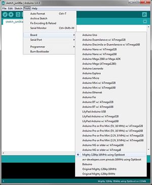
# [[File:Arduino_IDE_board_selection.jpg|thumb|right|Arduino IDE select correct board.]]In the IDE that opens, ensure that the proper hardware files for the Melzi controller have been installed by selecting Tools>Board and locate "Mighty 1284p 16 MHz using Optiboot". If not found in the list, return to [[Delta_Build_Overview:MOST#Software_to_download_and_install| overview]] and follow the instructions for installing the hardware files.{{clear}}
# Open the Arduino IDE.
# Connect the Melzi controller to the host computer with a USB A to mini B cable.
# [[File:Arduino_IDE_board_selection.jpg|thumb|right|Arduino IDE select correct board.]]Ensure that the proper hardware files for the Melzi controller have been installed by selecting Tools>Board and locate "Mighty 1284p 16 MHz using Optiboot". If not found in the list, return to [[Delta Build Overview:MOST| overview]] and follow the instructions for installing the hardware files.{{clear}}
# Ensure that the Arduino IDE has selected the correct communication port by selecting Tools>Serial Port. If you don't know which port it uses, first look at the available ports without the board connected. Then close the menu and connect the board. Select the port that newly appeared. The name of the port depends on your operating system:
# Ensure that the Arduino IDE has selected the correct communication port by selecting Tools>Serial Port. If there are multiple ports available, perform an internet search for "serial ports" for the operating system installed (e.g. "windows serial ports") and locate the port assigned to an FTDI USB-serial device. In Windows - go to the control panel and click on the unspecified device, and then the hardware tab and read what port it is.
#* '''Windows''' - Open device manager, locate FTDI USB-serial, Arduino, or similar under the Ports (Com & LPT)item and note the COM# in parentheses.
# Select File>Open and navigate to the location where the MOST printer firmware was saved and select Repetier.ino.
#* '''Mac OS''' - The port is called /dev/tty.usb followed by something (modem or serial and a code). There is also a port named cu.usb followed by the same thing; don't use that.
#* '''Linux''' - The port is called /dev/ttyUSB followed by a number, normally 0.
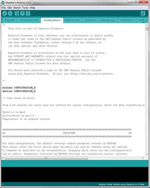
# [[File:Arduino_IDE_configuration.h.jpg|thumb|right|Open the configuration.h tab.]]Note that the IDE separates the different files that make up Repetier firmware into different tabs along the top of the edit pane. Locate the Configuration.h tab and click on it.{{clear}}
# [[File:Arduino_IDE_configuration.h.jpg|thumb|right|Open the configuration.h tab.]]Note that the IDE separates the different files that make up Repetier firmware into different tabs along the top of the edit pane. Locate the Configuration.h tab and click on it.{{clear}}
# The bulk of the definitions are logically named and documentation is thorough. Likewise, most of the settings will not need changing, but a few will. It is well worth the time to read through configuration.h and learn what some of the settings do - you will want to tweak your printer and this is the place where tweaking is done.
# The bulk of the definitions are logically named and documentation is thorough. Likewise, most of the settings will not need changing, but a few will. It is well worth the time to read through configuration.h and learn what some of the settings do - you will want to tweak your printer and this is the place where tweaking is done.
# Locate the line containing #define DELTA_DIAGONAL_ROD and change the number to that recorded during assembly of the tie rods. Magnetic jointed tie rods have a length of 250mm unless otherwise noted.
# Locate #define DELTA_DIAGONAL_ROD and ensure that its value is about 250 (there may be a value right of the decimal - it's OK to start with this value).
# Locate the line containing #define PRINTER_RADIUS and change the number to 175. This number may need adjustment if the linking boards were not properly spaced during assembly.
# Locate #define PRINTER_RADIUS and ensure its value is around 126.
# Upload the firmware to the Melzi controller (right arrow on toolbar or File>Upload). If the upload was successful, the printer should be ready for commissioning. [[Delta_calibration|Calibration]] is the last step that should be performed.
# Locate #define END_EFFECTOR_HORIZONTAL_OFFSET and ensure it is set to 0.
If you have trouble uploading double check your board choice and port, if correct and you still get this:
# Locate #define CARRIAGE_HORIZONTAL_OFFSET and ensure that it is also set to 0.
Binary sketch size: 56,256 bytes (of a 130,048 byte maximum)
# Upload the firmware to the controller (right arrow on toolbar or File>Upload). If the upload was successful, the printer should be ready for commissioning. [[Delta_calibration|Calibration]] is the last step that should be performed.
avrdude: stk500_getsync(): not in sync: resp=0x00
* In the message area at the bottom, the following message should appear:<br />
Then move the jumper to touch both pins of the autoreset at the bottom of the board and retry uploading.
Binary sketch size: 56,256 bytes (of a 130,048 byte maximum)
* If that message doesn't appear, there is something wrong with the code. Check the error message, which is probably about something you have changed.
* If an error appears after the above message, the code is fine but uploading didn't work. The following message is common:<br />
avrdude: stk500_getsync(): not in sync: resp=0x00
:: This means the computer cannot communicate with the Melzi. Possible reasons for this include:
:::* The autoreset jumper is not shorted.
:::* The wrong serial port is selected.
:::* The power selector jumper is set to VREG, but the 12V power supply is not plugged in. At this stage, not having this power plugged in is a good idea, so fix it by changing the jumper setting.
'''Troubleshooting Notes:''' The hardware selection entitled "mighty 1284p 16MHz using Optiboot" doesn't work for the rp3d.com version of the Melzi (v1.0/V2.0 hybrid). Instead download the sanguino hardware folder located here[https://github.com/reprappro/Marlin]. Unzip the file and copy the folder labeled "sanguino" into the Documents>Arduino>Hardware directory. After resetting Arduino IDE go to Tools>Boards>select Melzi 1284p 16MHz. This should work just fine.
*There are known problems compiling with the melzi hardware selected using the most recent release of Arduino IDE 1.6.0 on MacOSX: <br />
  Arduino: 1.6.0 (Mac OS X), Board: "Mighty 1284p 16MHz using Optiboot"
  Third-party platform.txt does not define compiler.path. Please report this to the third-party hardware maintainer.
  Error while compiling: missing 'recipe.cpp.o.pattern' configuration parameter"
*If you encounter try installing a previous version of Arduino IDE like 1.0.6, this has been shown to resolve the compiling error with MacOSX.
==Notes on Repetier Firmware for the Delta==
=Notes on Repetier Firmware for the Delta=
It's recommended that new printer builders use the firmware maintained by MTU-MOST at [https://github.com/mtu-most/most-delta github]. After having some experience, everyone is encouraged to download the in-the-wild Repetier firmware https://github.com/repetier/Repetier-Firmware. Note that there are two versions, a release (master) version and a development version. Since these exist in the public domain and almost anyone can change them, what is downloaded will not be configured for your printer - you MUST configure the firmware to work with your printer.
It's recommended that new printer builders use the firmware maintained by MTU-MOST at [https://github.com/mtu-most/most-delta github]. After having some experience, everyone is encouraged to download the in-the-wild Repetier firmware https://github.com/repetier/Repetier-Firmware. Note that there are two versions, a release (master) version and a development version. Since these exist in the public domain and almost anyone can change them, what is downloaded will not be configured for your printer - you MUST configure the firmware to work with your printer.
Line 88:
Line 117:
'''Setting EEPROM_MODE to anything other than 0 causes the firmware to load settings found in EEPROM - it will ignore changes to Configuration.h unless the value of EEPROM_MODE is changed.'''
'''Setting EEPROM_MODE to anything other than 0 causes the firmware to load settings found in EEPROM - it will ignore changes to Configuration.h unless the value of EEPROM_MODE is changed.'''
Remember in the RepRap Primer that firmware is software that runs on the controller. The firmware must be uploaded to the controller before subsequent steps can be performed.
Note
Windows operating system frequently has a hard time loading the correct Arduino drivers:
Open the Windows device manager (different for different Windows versions - do a web search to learn how to access it if you are unsure).
Look for an unknown usb device in the list - it might include something about FTDI in the device description.
If there is an unknown usb device, install the device driver (in most Windows versions, right click on the device entry and select 'Update driver').
DO NOT use automatic update - instead, select browse your computer.
The drivers are typically located in C:\Program Files\Arduino\drivers.
Depending on the version of Windows, this process may need to be repeated twice as there are actually two separate drivers for this single device (thanks, Microsoft).
Mac OSX can have problems with the Arduino driver
Problem 1: manifesting "serial port in use" errors when attempting to upload.
Run lsof | grep usbserial, which return something like: activhard 257 elmhirstka 4u CHR 19,1 0t15 607 /dev/cu.usbserial-A703B45K.
Take note of the process id - in the line above, it's the first number in the line (257).
In the terminal session, run kill (process #). In the example, above: kill 257
Problem 2: MacOSX doesn't recognize melzi as a USB device at all.
Solution: Install the most recent FTDI driver file located at [2]
Problem 3 problem uploading to board. programmer is not responding
Solution: Same as problem 2
""Problem"" IDE hangs at "Uploading..." for an indefinite amount of time.
Solution: TBD
Uploading Firmware to Controller with Arduino IDE
Use the file manager to navigate to the location where the MOST printer firmware was saved and open Repetier.ino. If your computer hides file extensions, it will simply be called repetier. It can be recognized as the only file having an Arduino icon.
Arduino IDE select correct board.In the IDE that opens, ensure that the proper hardware files for the Melzi controller have been installed by selecting Tools>Board and locate "Mighty 1284p 16 MHz using Optiboot". If not found in the list, return to overview and follow the instructions for installing the hardware files.
Connect the Melzi controller to the host computer with a USB A to mini B cable.
Ensure that the Arduino IDE has selected the correct communication port by selecting Tools>Serial Port. If you don't know which port it uses, first look at the available ports without the board connected. Then close the menu and connect the board. Select the port that newly appeared. The name of the port depends on your operating system:
Windows - Open device manager, locate FTDI USB-serial, Arduino, or similar under the Ports (Com & LPT)item and note the COM# in parentheses.
Mac OS - The port is called /dev/tty.usb followed by something (modem or serial and a code). There is also a port named cu.usb followed by the same thing; don't use that.
Linux - The port is called /dev/ttyUSB followed by a number, normally 0.
Open the configuration.h tab.Note that the IDE separates the different files that make up Repetier firmware into different tabs along the top of the edit pane. Locate the Configuration.h tab and click on it.
The bulk of the definitions are logically named and documentation is thorough. Likewise, most of the settings will not need changing, but a few will. It is well worth the time to read through configuration.h and learn what some of the settings do - you will want to tweak your printer and this is the place where tweaking is done.
Locate #define DELTA_DIAGONAL_ROD and ensure that its value is about 250 (there may be a value right of the decimal - it's OK to start with this value).
Locate #define PRINTER_RADIUS and ensure its value is around 126.
Locate #define END_EFFECTOR_HORIZONTAL_OFFSET and ensure it is set to 0.
Locate #define CARRIAGE_HORIZONTAL_OFFSET and ensure that it is also set to 0.
Upload the firmware to the controller (right arrow on toolbar or File>Upload). If the upload was successful, the printer should be ready for commissioning. Calibration is the last step that should be performed.
In the message area at the bottom, the following message should appear:
Binary sketch size: 56,256 bytes (of a 130,048 byte maximum)
If that message doesn't appear, there is something wrong with the code. Check the error message, which is probably about something you have changed.
If an error appears after the above message, the code is fine but uploading didn't work. The following message is common:
avrdude: stk500_getsync(): not in sync: resp=0x00
This means the computer cannot communicate with the Melzi. Possible reasons for this include:
The autoreset jumper is not shorted.
The wrong serial port is selected.
The power selector jumper is set to VREG, but the 12V power supply is not plugged in. At this stage, not having this power plugged in is a good idea, so fix it by changing the jumper setting.
Troubleshooting Notes: The hardware selection entitled "mighty 1284p 16MHz using Optiboot" doesn't work for the rp3d.com version of the Melzi (v1.0/V2.0 hybrid). Instead download the sanguino hardware folder located here[3]. Unzip the file and copy the folder labeled "sanguino" into the Documents>Arduino>Hardware directory. After resetting Arduino IDE go to Tools>Boards>select Melzi 1284p 16MHz. This should work just fine.
There are known problems compiling with the melzi hardware selected using the most recent release of Arduino IDE 1.6.0 on MacOSX:
Arduino: 1.6.0 (Mac OS X), Board: "Mighty 1284p 16MHz using Optiboot"
Third-party platform.txt does not define compiler.path. Please report this to the third-party hardware maintainer.
Error while compiling: missing 'recipe.cpp.o.pattern' configuration parameter"
If you encounter try installing a previous version of Arduino IDE like 1.0.6, this has been shown to resolve the compiling error with MacOSX.
Notes on Repetier Firmware for the Delta
It's recommended that new printer builders use the firmware maintained by MTU-MOST at github. After having some experience, everyone is encouraged to download the in-the-wild Repetier firmware https://github.com/repetier/Repetier-Firmware. Note that there are two versions, a release (master) version and a development version. Since these exist in the public domain and almost anyone can change them, what is downloaded will not be configured for your printer - you MUST configure the firmware to work with your printer.
All of OS 3-D printer firmwares were originally written for Cartesian printers and were subsequently modified for use with the increasingly popular delta printers. With some annoying exceptions, most all of the configuration settings for Repetier are located in Configuration.h. As of the current version (development v0.91) the following settings are required (assuming the printer is built per the BOM):
Virtually anything else can be tweaked to the user's liking. If you notice nothing changes upon uploading a new configuration:
Setting EEPROM_MODE to anything other than 0 causes the firmware to load settings found in EEPROM - it will ignore changes to Configuration.h unless the value of EEPROM_MODE is changed.