A modified Airtripper's extruder drive is used on the MOST Delta, you are encouraged to visit the developers page to learn more about it. Modifications consist of moving the filament path away from the drive gear and adding an infeed tube to facilitate live-changing. Other slight non-performance modifications were also made.
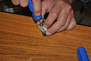
Ream the 3mm holes in the drive body and linking rod with a 3mm drill bit.
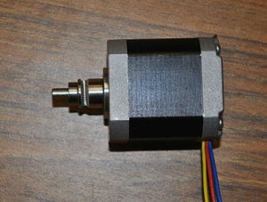
Motor with drive gear and bearing.Place the Mk7 drive gear on the motor with the set screw on the flat side of the shaft. Place the MR105z bearing on the shaft above the drive gear.
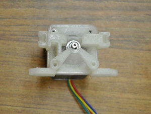
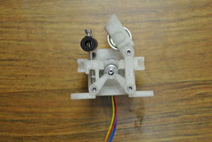
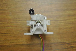
Motor with drive body properly oriented.With the motor laying on the table, wires exiting towards you, orient the printed drive body with the conical section towards you, as shown in the picture.
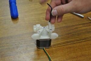
Drive body and linking rod attached to motor.Start the M3 x 6mm button head screw in the top-left hole.
Start the M3 x 25mm screw in the bottom-left hole.
Place the linking rod over the remaining mounting holes on the right side such that the screw head recesses face up. Start a pair of M3 x 30mm screws into the mounting holes.
Tighten all of the screws except for the floating end of the linking rod, firmly affixing the drive body to the motor.
Remove the base from the printed idler bearing shaft.Cut off the circular base from the printed idler bearing shaft and smooth and round that end of the shaft.
Assembled idler.Push the shaft through the 608zz bearing and snap the shaft and bearing into the idler cap.
The drive uses the small piece of rubber fuel line as a compression spring. Two holes must be drilled to align with the slots in the end of the printed idler housing. Lay the housing on the hose and mark the first hole with the 3mm drill bit. Drill through the fuel line at the mark.
Place washers on the two M3 x 45mm screws. Push one of the screws through the hole in the fuel line.
Using one screw to align idler housing. Place the idler housing back on the fuel line with the screw in a slot as shown in the picture and mark the location of the second hole with the 3mm drill bit.
Drill the second hole in the fuel line and push the remaining M3 x 45mm screw with washer through the hole in the same direction as the first screw.
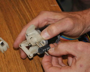
Attaching the fuel line to the drive - note position of M3 nut.Hose-spring attached.Getting the nuts started on the M3 x 40mm screws can be a challenge; laying the nut such that it rests against the screw boss as shown in the image can be helpful. Push the M3 x 40mm screws into their respective holes on the drive body and start a nut on each.
Attaching idler.Place the idler on its pivot (the scew under the floating end of the linking rod) and push the M3 x 40mm screws into the matching holes in the idler cap.
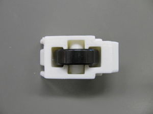
Completed extruder drive.Tighten M3 nuts on M3 x 40mm screws such that the hose is somewhat compressed.