| Line 60: | Line 60: | ||
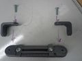
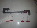
Using the .stl files above print out the following | Using the .stl files above print out the following | ||
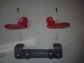
[[image:cfbracecomponents.jpg|thumb|Printed Components]] | [[image:cfbracecomponents.jpg|thumb|left|Printed Components]] | ||
#1 x bottom slider | #1 x bottom slider | ||
Revision as of 05:04, 6 December 2016
Under Construction
Brace for the treating of infants with club foot in East Africa
Project developed by [Blsavone]
Abstract
Problem
Club foot is a congenital, physical deformity that is characterized by infants being born with a foot turned inward or to the side. It is easily and typically treated in developing countries, but in rural, developing areas where treatment options may be less available, club foot can lead to life-long disability. It has been estimated that prevalence of clubfoot in Africa is approximately 2 in every 1000 births.
Solution

A 3D printable brace that can be used to treat children born with club foot. The brace is able to be adjusted in several different directions, can extend in stance-width, and has an open-toe design to allow for a variety of sizes. The stance widith is measurable in 0.5cm increments, and both angles can be adjusted to the nearest 15 degrees.
As with most braces used for the treating of club foot, infants and small children have their feet locked into the foot pads with straps (improvisable with cloth or velcro), and then sleep with the braces on their feet. Over time, the braces can be slowly adjusted to correct the positioning of the feet.
Bill of Materials
- PLA plastic filament
- 2 x 1/4-20 1" carriage bolt
- 1 x 1/4-20 1.25" carriage bolt
- 1 x 1/4-20 0.75" carriage bolt
- 2 x 1/4-20 1" hex head bolt
- 6 x 1/4-20 hex nut
Tools needed for fabrication of the OSAT
- MOST Delta RepRap or similar RepRap 3-D printer
Skills and Knowledge Necessary to Make the OSAT
None
Technical Specifications and Assembly Instructions
Print Instructions
For all printed components
Material: PLA
Layer Height: 0.2mm
Shell Thickness: 1mm
Fill Density: 80%
Print Speed: 40 mm/s
Printing Temperature: 185 C
No supports necessary.
Total Printing Time: 13+ hours
Assembly time: >5min
Assembly Instructions
Using the .stl files above print out the following

- 1 x bottom slider
- 1 x top slider
- 1 x closing bracket
- 2 x angle bracket
- 2 x foot pads
- 5 x flattened knob
- 1 x raised knob
- Assembly of Foot Brace
-
-

-
-
Place the 1 inch bolts through the angle brackets and existing assembly
-
Place 3 of the flattened knobs and the one raised knob on the carriage bolts and tighten
-
Place the 1 inch hex head bolts through the foot pads and attach them to the angle brackets.
-
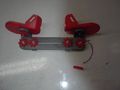
Tighten the remaining two knobs onto the hex head bolts


Common Problems and Solutions
- Be sure to place the nuts into the printed dials as soon as the dials are printed. The plastic is still soft as it cools, and due to its tight fit, it is difficult to place the plastic once it has cooled.
- Some of the holes may be a tight fit. Be sure to have a 1/4 inch drill bit handy if necessary.
Cost savings
- If your solution is not a low cost one then it is not really appropriate.
- Estimate your costs
- Find a commercial equivalent
- Calculate $ savings and % savings
References
- The sources of information (e.g. engineering handbooks, journal articles, government documents, webpages, books, magazine articles etc.). References should use the <ref> </ref> and <references/> tags and can be in any format but should include all the information necessary for someone else to find the same information you did. For example: [1]
- ↑ web page: Department of Energy (DOE) Landscaping and Energy Efficiency, DOE/GO-10095 (1995) Available: http://www.eren.doe.gov/erec/factsheets/landscape.html
Based on the developmental needs addressed (e.g. food, heat, electricity, clean water, health care, etc.) be sure to label your device in the proper categories e.g. use [[Category:Water]]. Be sure to categorize your device so that it will be easy to find – for example “Low voltage connection basics” is categorized in [[Category:How tos]] [[Category:Electricity]] [[Category:Electric lighting]].