CNC Router Lubrication and Chip Clearing
Project developed by JBailey, Jrjarvis, Q. I. Kaspriak
Template:Statusboxtop Template:Status-design Template:Status-prototype You can help Appropedia by contributing to the next step in this OSAT's status. Template:Boxbottom
Abstract
The goal of this design is to allow a lubrication and chip clearing module addition to a CNC router. This system consists of an external unit which served to feed the air and lubrication with an actuating arm mounted on the spindle to better direct the fluid/air onto the tool piece. This simple and easy solution would allow individuals to use their CNC Router with metal.
Bill of Materials
| File Name / Part | Quantity | Source | Unit Price | Cost |
|---|---|---|---|---|
| CNC Mount | 1 | hyperlink | ~ $0.33 | ~ $0.33 |
| Socket Ball Long Adjusted | 2 | YouMagine | ~ $0.13 | ~ $0.26 |
| Socket Flange | 2 | YouMagine | ~ $0.08 | ~ $0.16 |
| Ball 40mm Ball Ver | 1 | YouMagine | ~ $0.12 | ~ $0.12 |
| Locking Nut | 4 | YouMagine | ~ $0.03 | ~ $0.12 |
| End Hose Clip | 2 | YouMagine | ~ $0.03 | ~ $0.06 |
| Clip | 1 | YouMagine | ~ $0.01 | ~ $0.01 |
| Parametric Peristaltic Pump | 1 | YouMagine | ~ $1.13 | ~ $1.13 |
| 3 ft of Tubing (3/8" OD) | 1 | Tubing | ~ $2.00 | ~ $2.00 |
| 8 in of Soft Tubing | 1 | Surgical Tubing | ~ $8.50 | ~ $8.50 |
| 28BYJ-48 Stepper Motor (for Peristaltic Pump) | 1 | Adafruit | ~ $4.95 | ~ $4.95 |
| Motor (for Fan) | 1 | hyperlink | ||
| Arduino UNO | 1 | Arduino | ~ $22.00 | ~ $22.00 |
| ULN2003 Stepper Motor Drive | 1 | Elecrow | ~ $1.78 | ~ $1.78 |
| Total | 13 | - | - | ~$44.37 |
Tools needed for fabrication of the OSAT
- MOST Delta RepRap or similar RepRap 3-D printer
- Soldering Iron to use filament welding method to connect parts
- Use solding iron to melt filament together. A short piece can be ran through holes and melted on either end. Another option is to melt along the edges where two parts meet.
Skills and Knowledge Necessary to Make the OSAT
- Use for FreeCAD to adjust .FCSTD files FreeCAD Website FreeCAD Wiki
- The Basics of 3D Printing The Free Beginner’s Guide
- OpenSCAD OpenScad Website
Technical Specifications and Assembly Instructions
| File Name | Print Time | Layer Height | Material | Infill |
|---|---|---|---|---|
| CNC Mount | 1:24 | 0.15 mm | Hatchbox PLA | 25% |
| Socket Ball Long Adjusted | 0:48 | 0.1 mm | Hatchbox PLA | 25% |
| Socket Flange | 0:34 | 0.1 mm | Hatchbox PLA | 25% |
| Ball 40mm Ball Ver | 0:49 | 0.1 mm | Hatchbox PLA | 25% |
| Locking Nut | 0:15 | 0.1 m | Hatchbox PLA | 25% |
| End Hose Clip | 0:14 | 0.1 mm | Hatchbox PLA | 25% |
| Clip | 0:05 | 0.1 mm | Hatchbox PLA | 100% |
| Parametric Peristaltic Pump | 5:00 | 0.2 mm | Ultimaker PLA | 25% |
| Total | 9:09 |
It is assumed that the "first step" before these instructions is to acquire all materials needed from the Bill of Materials.
- Arm Sub-Assembly
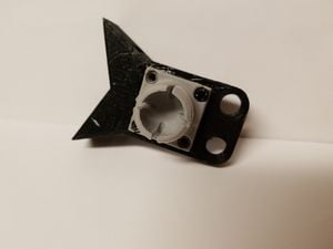
CNC Mount and Socket Flange 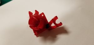
End Clip Top 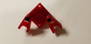
End Clip Bottom 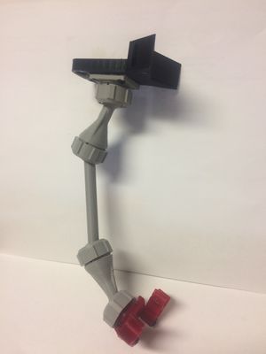
Fully Assembled Arm
- Parametric Peristaltic Pump Sub-Assembly
- x
- y
- Cut tubing to appropriate length and attach
- Fan Sub-Assembly
- x
- y
- Cut tubing to appropriate length and attach
- Final Assembly
- Place Parametric Peristaltic Pump Sub-Assembly in Box
- Secure to box with ?
- Place Fan Sub-Assembly in Box
- Secure to box with ?
- Run tubing from two assemblies to the "CNC Mount". Feed through the holes and place in "End Hose Clip"
- [[File:Arm Final Final.JPG|thumb|center|Final Arm Assembly]Adjust arm to angle tubing in the desired direction and tighten "Locking Nut"s.


Common Problems and Solutions
- n/a
Cost savings
| Commercial Cost | Our Cost | $ Savings | % Savings |
|---|---|---|---|
| $900-$2000 | $44.37 | $855+ | 95.1% |