Construction manual of a bucketpump Developed in cooperation with Codéart and the workshops-schools of Camp Perrin
Philippe Carlier Project engineer ISF
Guide to manufacture a bucketpump [1] Collection "Technical Manuals"
Manual directed by ISF with the support of the Directorate-General for International Cooperation (DGCI)
Ingénieurs Assistance Internationale - Ingénieurs sans Frontières 2002 http://www.isf-iai.be mail@isf-iai.be Avenue du Marly, 48, 1120 Brussels - Belgium
We thank all the people without whom this book could have not seen the light of day, and in particular: John Franco and Sprumont Gattigo (AECP), Roger Loozen (Codéart) and Didier Beaufort (COTA).
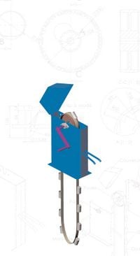
Technical sheet Max. pumping speed: > 20 l/min Max. working depth: > 60 m Pumping speed/working depth: depending on the depth of wells: see graph Drivetrain: manual but can be powered with minor modifications. Use: rather reserved for domestic use Maintenance: only lubrication of bearings (optional) Features: low cost manufacturing, technical, simple manufacturing, robust Shelf life: > 5 years with intensive use
Construction manual of a bucketpump.
Introduction
This manual is intended for all workshops in the South who wish to put in place the manufacturing of pumps which are simple, robust and cheap.
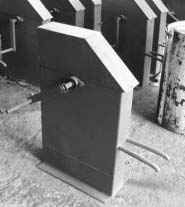
Indeed, the pump described in this guide was developed in Haïti by the workshops-schools of Camp Perrin which assures it is well suited to the constraints of most countries where the there is a lack of technical expertise, both in terms of manufacturing as its use. Before starting of building this model, many tests were performed on different types of well pumps, and many diiferent technical solutions have been considered: this manual will enable other workshops to avoid following the same path and reproduce the same mistakes.
The manufacture of this model of pump requires a minimum of equipment. It can therefore be created by workshops with limited equipment. To the furthest possible extent, the materials used are cheap, and easily obtainable materials, irrespective of the location. Finally, this pump requires but very little maintenance.
General / Efficiency
Why choose a bucketpump ?
- A bucketpump is both easy to manufacture, to install and requires onlylittle maintenance, while providing quite acceptable pumping speeds.
- The system removes all the elements that generally pose problems and asks for maintenance that is also found in conventional pumps, strainer, foot valve, seals, air or waterdevices under pressure, ...
- All the mechanical parts are accessible from above, the repairs thus do not require to descend to the bottom of the well.
How does a bucketpump work ?
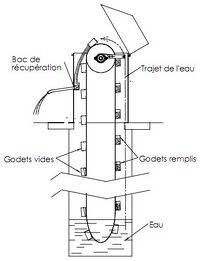
The bucketpump consists of a belt without end (= closed on itself) on which buckets are fixed at regular intervals. One end of the belt plunges into the bottom of the well while the other end, connected to a pulley, is above ground. When turning the pulley (in the correct direction), the empty buckets (see left part on drawing) move down towards the bottom of the well, with the bucket facing the bottom. They then plunge in the water where they are replenished. When they re-emerge, filled with water, the bucket is reorientated towards the sky. When they arrive at the top of the well, the movement of the belt around the pulley makes the bucket tip. Its content is poured into a recovery tray, directly connected to the evacuation tube at the outlet from where the user can reclaim the water. To better understand the mechanical operation of the pump, it may be useful to examine the detailed drawing in Appendix 1.
Pumping speed and operating depth
The optimal pumping speed of the pump depends on the depth of the well. Indeed, the spacing between equal buckets is dependant on the the depth of the well, and the amount of filled buckets to raise. Thus the deeper the well is, the more spacing there must be between the buckets so that the amount of water that must be pumped up remains reasonable. (so as not to tire the user). Figure 3 shows the spacing and the optimal pumping speed in function of the well depth, to maintain a force on the crank that is still acceptable for a child to manage (less than 5 kg). This figure is purely theoretical because a workshop can not produce a different belt for each well. For example at Camp Perrin, the distance between the buckets is 30 cm. However, for depths exceeding 40 m it increases to 60 cm (actually the belt is always perforated every 30 cm, but we only attach a one bucket every two holes).
In the end we can state that the pump speed varies between 8l/minute and 22l/minute for depths from 5m up to 60 m. This model of pump was installed in wells with depths up to 60m. The problem of wells with great depths is the need to have very straight vertical wells (the belt may not touch the wall of the well) rather than the operation limits of the pump itself 2.
Pump speed (l / min) Depth (m) Pump speed Spacing Spacing between buckets (cm)
Indeed, when digging wells, the perception of verticality is lost by the person who digs it because of the depth and the narrowness of the wells. The method of excavation as well as a description of the equipment used at Camp Perrin is available on the website: www.codeart.org
Historical development of the pump by the workshops-schools of Camp Perrin
Before the adoption of the bucketsystem by the workshops-schools of Camp Perrin, different types of pumps have been evaluated. Either these pumps demanded technologies that were hardly compatible with the equipment of countries in the South, or they were not robust enough for the difficult environmental conditions. Several ancient types of manufacturing for the pumps have been researched before and during the development, to take advantage of lessons learned in the past and to compare solutions found by different people.
The bucketpump is not the only type of well pump. Here is an overview of other systems based on a similar principle.
- The multi-band pump (see the vintage advertising in Appendix 8: Pump "Caruelle"): This is a metal flat belt on which a metal band is fixed with a large number of ripples. Each cell forms a ripple where the water comes in and is fixed by capillary action. It does not leave until it reaches the pulley above by deforming the cells on the curvature of the pulley. The multicellular band is difficult to make and is relatively expensive.
- There is also a springed variant that uses the same principle of capillary action. Here, the multicellular band is replaced by a spiral spring that turns around a chain. This pump is relatively easy to make, but quite difficult to repair if the chain is broken.
- The foam band pump (see vintage advertising in Appendix 8: Pump "Champenois"): The belt consists of two nylon ribbons between which a band of foam is stuck. In the space of the submerged pulley, the strip of foam reduces in size under the effect of the weight of the pulley, expelling the air it contains and filling with water when it relaxes (no longer subject to the weight of the pulley). The opposite phenomenon occurs when water reaches the above pulley: the band compresses and the water is expelled.
- The cup pump (see vintage advertisement in Appendix 8: Pump "Masure"): the pumping of the water is done through circulars cups centered on a cable. These specially shaped cups take up water by direct uptake and by capillary action.
- The bucket pump (see vintage advertisement in Appendix 8: Pump "Dragor"): This system is the most robust, the easiest to make and the least expensive. It is for these reasons, that this system has been adopted by workshops-schools of Camp Perrin. This system is very efficient and has proven itself. In addition, it has the advantage of reintroducing oxygen into the well, thus improving the sanitary quality of water (by oxidation of impurities).
A number of drawings that can be found include a tension pulley for the bottom of the well. Tests done at Camp Perrin have highlighted the inutility of this pulley with this type of pump. Others recommend using a pulley fitted with an edge to prevent the deattachment of the belt. In practice it are however precisely those edges that provoke the release of the belt. Using a pulley with a convex profile is much more reliable: during several years, on several hundred pumps installed by the workshops, no belt has ever deatteched from the pulley. Once the belt deviates from the center of the pulley, the curved profile and rotation movement return it automatically to the center (except in cases of friction on the walls of the well or in cases of abrupt reverse movement due to the absence of a return-brake).
Manufacturing
Description of the elements of the pump
Materials ... for the manufacturing 1 sheet 1200 x 1600 Th. 4 mm Profile 40 x 30 L345 mm Flat iron 40 x 10 L320 mm Iron round Ø14 x L150 mm Iron round Ø16 x L100 mm Iron round Ø25 x L215 mm Iron round Ø30 x L400 mm Tube Ø20 Th. 2 L60 mm Tube Ø23 Th. 2 L600 mm Tube Ø25 Th. 3 L60 mm Tube Ø30 Th. 2 L170 mm Tube Ø60 Th. 1.5 L100 mm 6 nuts DIN 934 M12 4 screws DIN 933 M12 x 40 2 screws DIN 933 M12 x 50 12 washers DIN 125 M12 1 molded pulley 2 bearings NTN UCFL216 (or equivalent) ... for galvanizing Water HCl NaOH (optional) Na2CO3 (optional) FeCl2 (optional) detergent Zinc salt to the fluxage (ZnCl2 and NH4Cl). Materials Pliers Welding post Anvil Galvanizing furnace (drawings attached) Récipients in plastic (not PVC)
Lid Construction Pulley Bearings Crank Ratchet Belt Buckets Reclaimation tray
The construction
(See detailed drawings and sheet designs in Appendix 2) The sheets used for the building of the construction have a thickness of 4 mm (thicknesses from 3 mm to 6 mm are acceptable depending on the locally available products). As aguideline, we can built about 2 constructions with a sheet with metricalstandards (3000x1500 mm), and 1.5 with a sheet with English standards 8 ft x 4 ft. The construction must be protected from corrosion by paint (the ideal would be galvanization). The water reclaimation tray may seem fairly small, but experience has shown that a larger tray does not recover any more water and could pose problems for the free movement of the belt.
The crank and bearings
(See detailed drawings in Appendix 3) Next, the rectangular profile of the crank manufactured at Camp Perrin, was a hollow pipe. Given the early wearing of this part on most installed machines, we recommend using a thick-walled pipe, or full profile.
The bearings are modified bearings with an inside diameter of 30 mm. (see Figure 6). The bearings used at Camp Perrin are bearings of the NTN brand, model UCFL206 (manufactured in Japan). There are also a variety of similar bearings with other suppliers (FAG model FG16206, SKF model FYTB30FM ,...)
The pulley
(See detailed drawings in Appendix 4) The pulley used for the training of the belt is made of cast iron. This is the only piece that is made in a foundry. The workshops that not have this technology will have to outsource this part or mechanically solder it. In this case, we will make sure to keep the convex curvature at the outside of the pulley, since it is the latter which assures the auto-centering of the belt. This curvature could ,in this case, be obtained by turning or forming.
The pulley is equipped with a return-brake (ratchet wheel). An alternative is to decouple the ratchet wheel from the pulley's body and to boulonner afterwards: You can make the sawshaped teeth by starting-off with a thick sheet. In this case we make straight teeth and in lower number to simplify manufacturing.
Return-brake ratchet
(See detailed drawings in Appendix 5) This ratchet prevents the crank to turn backwards when the user stops pumping. Indeed the buckets of the part that rises the belt are still filled, while those of the descending part are empty. This imbalance tends to turn the pulley in reverse direction. We prevent this for three reasons:
- The brutal movement of the crank could injure someone;
- the water which is contained in the rising buckets does not redescent and pump is ready to pump immediately for the next user;
- Avoiding the risk of déjantage of the belt.
The belt and the buckets
Manufacturing of the buckets
(See attached drawings in appendix 6) The buckets can be made from perforated and welded metal sheets or simply from pipes depending on the local availability. If we choose for the perforated sheet solution, we may use the simple tools shown to the right for the bending.
We weld a round cut sheet to close the bottom of the bucket. To ensure a good fixing of the bucket to the belt, we make a sheet on it (for example by forging on the square bigorne on an anvil: see Figure 12), then we drill fixation holes on this sheet using a template.
Galvanizing the buckets Material: plastic receptients, zinc furnace, water, HCl, detergent, zinc, salt for the fluxage (ZnCl2 and NH4Cl) and optionally NaOH, Na2CO3, FeCl2. The galvanizing serves to protect the buckets against corrosion. It consists of depositing a thin film of zinc on the iron.

In certain areas where these products are difficult to obtain in small amounts, the best solution is to direct yourself to local factories or workshops that posses large amounts of galvanized units in order to buy a part of their raw material.
Caution, this step should be conducted in a well ventilated area. Here are the steps that must be followed:
- Alkaline degreasing: soak the buckets for 5 to 30 minutes (depending on their degree of dirtyness) in water at 70 °C containing ideally diluted caustic soda, baking soda and
detergents. For this; you may use a commercial preparation called "Ferroclean 7511". Note that in Camp Perrin, we work more simple; namely by soaking the buckets in water of ambient temperature containing washing powder or diluted dishwashing liquid.
- Rinsing with demineralized water or, more simply, with clean water at room temperature.
- Acid pickling: soak the buckets for 5 to 30 minutes in ambient temperature water in which we add 35 to 90 grams per liter of FeCl2 (iron chloride) (for the reduction of oxides), 130 to 180 grams per liter of HCl (hydrochloric acid) and inhibitor H 436. In Camp Perrin, we simply use two baths of hydrochloric acid at 18 ° Baumé. We commence by soaking the buckets in the used bath, an then in the clean bath. When the latter becomes dirty, we replace the dirty bath. The dirty bath is also used to recover missed buckets after the galvanizing step has been properly doneitself. If we proceed in recovering these missed buckets we must be very careful not to release hydrogen gas (highly flammable).
- Rinsing with demineralized water or, more simply, with clean water at room temperature.
- Fluxage: the fluxage or passivation serves to prevent the rusting of the buckets when we dry them before soaking in molten zinc. For this, they are soaked for 5 to 30 minutes in a bath with 350g of salt per liter. The salt will have any of the following compositions:
- either the salt of Cook (38.5% of ZnCl2 and 61.5% of NH4Cl)
- or triple salt (46% of ZnCl2 and 54% of NH4Cl)
- or double salt (56% ZnCl2 and 44% of NH4Cl)
Optionally, you can also add a surfactant in the bath (Novamax FX701) at 0.5 to 1 ml per liter.
- Drying: we must dry the buckets face down to remove any water, in order to avoid explosions caused by the sudden spray of water in a bath of molten zinc. At Camp Perrin, we put the buckets on a place near the furnace to dry them.
- Galvanizing: for a proper galvanizing, we soak the buckets in a bath of molten zinc (450 °C). We must leave the buckets sufficient time to allow them to take on the temperature of zinc (approximately 30 seconds). On the buckets, the zinc should no longer form a paste but be as liquid as water. When we plunges the buckets in the zinc, we must do so with their face upwards to avoid that the trapped air does not suddenly expands, causing burning projections. We will also regularly skim the surface of the bath filled with NH4Cl to not contaminate the buckets.
- Cooling of the buckets.
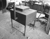
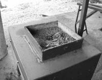
At Camp Perrin, galvanizing is carried out through the device shown in Figure 13. One of the walls of the furnace is a battant mounted on charnieres which allows the introduction of a burner (on gas) in the structure of the furnace.
The belt
The belt is a belt of 50 x 5 mm section from flexible polyester reinforced with stronger polyester. We may also use conveyorband belts 4 with the comparable performances. The length of the belt is equal to the depth of the well plus the height of the axis of the pump minus the height reserved for filing, the whole being multiplied by two: where Lb: length of the belt; D: depth of the well; Hp: height of the axis of the pump in connection to the ground; Hd: height of depot (security height in case of silting of the well).
The assembly of belt and buckets

Once the buckets are zinced, we can fix them to the belt. A good spacing between the buckets for a depth of 30 m is 300 mm. For greater depths, we increase the spacing of the buckets (eg wells of 60m: 600 mm spacing) to maintain a reasonable amount of water to hoist. In this case, we obviously reduce the pumping speed with a single move (see Figure 3 p.6). The holes are drilled using a template (see illustration). The fixing of the buckets must be done by means of special screws with a flat head in order to not damage the belt and to not hinder the movement of the belt on the pulley (see figure 15). The screws are the M6 x 20 of the DIN 15 237 norm 5. The domed bolt allows to avoid damaging the belt. The belt is closed on itself by means of the same screws (4 boulons)
On-site installation
We place concrete blocks on top of the well. In this step, we should take two essential precautions:
- ensuring that the blocks and principally, the here described perforated part is elevated in connection to the ground to ensure that water runoff and dirt can not contaminate the water well.
- If the well is not completely vertical, it is possible that the optimal position of the pump is not at the center of the hole: we will put the pump in such fashion that the belt is the furthest possible away from the walls and along the entire length of the well.
Maintenance
The only maintenance that the pump requires is regular lubrication of the bearings. We therefore advise to provide a lubrication burette to the customer when we sell a pump if we want to ensure a long life-expectancy of the machine. In practice nevertheless, the pump lasts several years without problem with no lubrication at all.
The supplier for the AECP and the particulars of the conveyorbelt: Dunlop-Enerka Belgium SA Bvd des Combattants, 64 - 7500 Tournai - Belgium Dunloplast conveyorbelt 315/1 width 50mm coatings 1.5 + 1.5 mm - white PVC - FDA Quality The supplier for the AECP and particulars of their screws: BECHTEL Gmbh - Hahnerbergerstrasse, 257 - 42 349 WUPPERTAL in Germany Tel: +49 (0) 202 40 30 36 - fax: +49 (0) 202 40 34 81 e-mail: info@bechtel-wuppertal.de Website: www.bechtel-wuppertal.de Elevatorbecherschrauben M6 x 20 komplett, vers. Kopf, 2 Nasen ähnlich DIN 15 237, Kopf-O c. 18mm verzinkt.
Appendixes
ANNEX 1: EXPLODED VIEW OF THE PUMP...13 ANNEX 2: DRAWING OF THE CONSTRUCTION.15 APPENDIX 3: DRAWING OF THE CRANK.....16 APPENDIX 4: DRAWING OF THE PULLEY....21 APPENDIX 5: DRAWING OF THE RATCHET...23 APPENDIX 6: DRAWING OF THE BUCKET....24 APPENDIX 7: DRAWING OF GALVANIZATION FURNACE..25 APPENDIX 8: DECOMISSIONED PUMPS..27
To get the free version (with annexes) on paper or electronic format you can just send us an email to following emailaddress: mail@isf-iai.be
