| Line 47: | Line 47: | ||
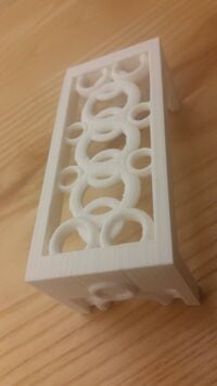
| Second attempt at Celtic drawer handle, enlarged the file and added different geometric designs. Working blender and stl file attached. | | Second attempt at Celtic drawer handle, enlarged the file and added different geometric designs. Working blender and stl file attached. | ||
| [http://www.appropedia.org/New_drawer_handle_nordic file] | | [http://www.appropedia.org/New_drawer_handle_nordic file] | ||
|- | |||
| | |||
|- | |||
|- | |||
! DSLR Cannon telescope adapter | |||
|- | |||
| [[Image:Telescope adapter.png|200px]] | |||
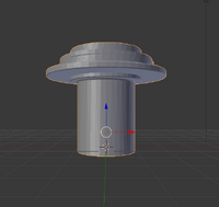
| A blend file of the telescope adapter I made for a 1.25" telescope. Hopefully the printed version works, otherwise its back to designing. | |||
| [https://www.dropbox.com/s/zw7jtudvyjuo08u/telescope_adapter.blend?dl=0 file] | |||
|- | |- | ||
|} | |} | ||
Revision as of 02:12, 31 March 2017
Overview
This is a web page for the Engineering 242s personal Appropedia project. Its goal is to document our experiences and progress as we accomplish the activities in this class. I for one, will be focusing on the open source side of things discussing the implications of this technology and the activity we do in class. I will also be sharing all source files of the projects I work on as well as discussions surrounding each one.
Description
Why 3-D Printing? A recent report from data company Wanted Analytics found that in one month 35 percent of engineering job listings from a variety of fields, including biomedical, software, and transportation industries, required applicants familiar with 3-D printing.
Why Open Source?
Having personally helped open source projects come to life in the past I am no stranger to how they operate. However this is the first time I have been involved with a project as developed as the 3D printing community is. Most of my past contributions are community coding projects on *GitHub[1]. What attracts me to open source technologies is the ever evolving and entirely open-ness of them. You have the ability to see every part of a piece, rather than just the parts the developers want you to see. As a self declared Tinkerer, I love tearing something apart to view how ALL of it works, not just select parts.
What I plan on doing with my Jellybox printer is the class projects and doing research into cheaper alternatives to scientific gear for microscopes and telescopes. Later on once I build my own 3D printer I would love to delve into board game and miniature figurines.
Projects
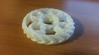
| The gear project 1.0 | |||
|---|---|---|---|
|
This was my first print attempt, it turned our rather well. After calibrating my printer I loaded in this file and set it loose. | file link: | |
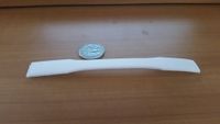
| Mechanical fork project 2.0 | |||
|
Second official print with the Jellybox printer, designed to test the tinsel strength of our designs. Original design had flaws when attempting to interlace it with our stress testing machine. Will update with further details. | file | |
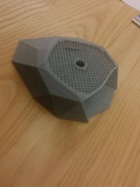
| Rock climbing grip 1.0 | |||
|
First attempt at printing the rock holder grip, top failed due to a loose belt. | file | |
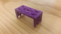
| First attempt at Celtic drawer handle 1.0 | |||
|
First attempt at printing Celtic drawer handle assignment, failed due to incorrect geometry within the file. NOTE: incorrect file uploaded for comparison | file | |
| Working attempt at Celtic drawer handle 2.0 | |||
|
Second attempt at Celtic drawer handle, enlarged the file and added different geometric designs. Working blender and stl file attached. | file | |
| DSLR Cannon telescope adapter | |||
|
A blend file of the telescope adapter I made for a 1.25" telescope. Hopefully the printed version works, otherwise its back to designing. | file |
MiniMech Mechanical Fork Testing
Hypothesis
My hypothesis is that the horizontally printed coupons will be ultimately stronger when compared to the vertically printed coupons. Further hypothesis on the types of print settings and their control over print quality: slower flow rates with higher temperatures will yield a stronger print while faster flow rates with lower temperatures will yield weaker bonds between layers thus resulting in weaker print quality.
Method
Stress testing the coupon was accomplished by the use of a vertical tensile stress tester clamped on opposite ends of the coupon and then applying continuous increments of force until the unit broke. The original MiniMech project called for test coupons with dimensions of 180 mm x 13 mm with a thickness of 3.2mm with a deviation of +/- 0.05mm for allotted change in unit size. These dimensions are in accordance with standard ASTM design protocol and would have been compared with other research data upon completion of the project. When these test coupons were inserted into the PASCO test machine they proved too tough and the clamps could not get a tight enough grip in order to apply enough force to break them. The test coupons kept on slipping out of the clamps and thus a redesign had to be constructed in order to comply with our limited testing equipment. These new test coupon designs were modeled off of the supplied coupon by the manufacture of the stress testing machine. They were much smaller and slimmer in size than our ASTM standardized coupons. They worked flawlessly in the machine with results as expected when compared against our hypothesis. The coupons that were slower, with higher temperatures performed better than the faster, lower temperature coupons.
Data Charts for MiniMech Project
| Name | Force (RD$) | Position | |
|---|---|---|---|
| Base Test, (210f) normal temp, normal flowrate: Mh0 | 221n | 2.07mm | |
| Fast Print, (200f) lower temps, faster flowrate: Mh1 | -79n | 0.0065mm | |
| Slow Print, (220f) higher temps, slower flowrate: Mh2 | -225n | 1.88mm |
| Name | Force (RD$) | Position | |
|---|---|---|---|
| Base Test, (210) normal temps, normal flowrate: Mv0 | -150n | 3.15mm | |
| Base Test, (210) normal temps, normal flowrate: Mv0 | -179n | 2.75mm | |
| Base Test, (210) normal temps, normal flowrate: Mv0 | -201n | 2.11mm |
Conclusion
Data was uploaded to a class group excel sheet; with limited accounts uploaded data it appeared that for the majority of users they experienced similar test results when compared against my own. With each individual testing different elements in each print and the printer quality control taken into account a rough estimation of the data can be gathered. From the 18 entries at time of writing the average max tensile force applied to the vertical test coupons was: -124.667n, with an average elongation of -194.667mm’s. For horizontally printed coupons similar results were gathered when compared against our hypothesis. Max tensile force: 194.667 with an average elongation of -1.7808944mm. Thus we can conclude that the horizontally printed coupons were stronger in the tensile strength testing however the vertical coupons proved more prone to elongation in similar tests. In the future in order to comply with ASTM standards a modified clamp should be made, this would allow us to enter our data into official ASTM testing coupon databases.
Rock Climbing Project
One of our assignments was to design a rock climbing grip, having extensive rock climbing experience I knew roughly the type of shape I wanted to create. I first started with creating a design in mudbox, a free trial alternative to Zbrush. Within this application I modeled a nub style grip which would've worked perfectly if I was able to export the object to blender for stl transformation. However this was not the case and after a few hours of mucking around with file extensions I decided to start over explicitly in blender.
There I created a ledge style grip, gave it a screw hole and printed it. On my third print attempt after a belt tightening I managed a successful print.
Videos
| jellybox print time lapse |
|---|
Error in widget YouTube: Unable to load template 'wiki:YouTube' |
Error in widget YouTube: Unable to load template 'wiki:YouTube' |