Automated Plastic Grinder/Recycler
Project developed by Michael James WestonButler Jhbell
Template:Statusboxtop Template:Status-design Template:Status-prototype You can help Appropedia by contributing to the next step in this OSAT's status. Template:Boxbottom
Abstract
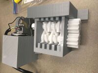
There is a very large need for an affordable and strong plastic grinder. With current models on the market that are made from steel and require numerous parts and fittings costing upwards of $400, cheaper versions could be appealing to customers. We have created a mostly 3D printed grinder using a combination of PLA and Polycarbonate parts and a few other pieces of hardware. This design utilizes two hex shafts with 5 teeth per shaft, encased in a solid 3D printed box. The shaft is driven using a windshield wiper motor which is powered by an old computer power supply. This shredder design takes a lot of the guess work of tolerances and proper fits out of the equation.
There are some plastic grinders that are 3D printable currently, but they are not as robust as this design, nor are they automated.
- Picture of completed print using your printer

Bill of Materials
BOM
- DeltaBot Athena II Printer
- PLA Filament - 1 roll (any of the common 3d print filaments will work)
- Polycarbonate Filament - 1 roll (Polycarbonate is needed here for high strength teeth)
- Windshield wiper motor
- 12 Volt computer power supply
- 1- 6mm Wingnut
- The following link is to all openSCAD and STL files related to this project: https://www.youmagine.com/designs/grinder-shredder
Tools needed for fabrication of the OSAT
- MOST Delta RepRap or similar RepRap 3-D printer
- Wire Strippers
- Adjustable Wrench
- Drill
- Drill Bit
- 6 Screws
Skills and Knowledge Necessary to Make the OSAT
- Ability to run Cura or another Slicing program
- Operate Deltabot Athena II
- Ability to splice together positive and negative wires from motor to power supply
Technical Specifications and Assembly Instructions
- Provide directions for print/assembly - be detailed enough in your “how to” to ensure that someone could construct the device from your description. Consider the elegance of IKEA like instructions.
Box Cura Settings
- 45% Infill
- Tri-hexagonal Infill
- 150 mm/s print speed
- 200 C print temp
Motor Mount Cura Settings
- 25% Infill
- Tri-hexagonal Infill
- 150 mm/s print speed
- 200 C print temp
Shaft Cura Settings (Polycarbonate print)
- 95% Infill
- Tri-hexagonal Infill
- 60 mm/s
- 255 C print temp
- 90 C bed temp
Teeth Cura Settings (Polycarbonate print)
- 95% Infill
- Tri-hexagonal Infill
- 60 mm/s
- 255 C print temp
- 90 C bed temp
Wing nut coupler Cura Settings (Polycarbonate print)
- 95% Infill
- Tri-hexagonal Infill
- 60 mm/s
- 255 C print temp
- 90 C bed temp
Bearing Cura Settings
- 100% Infill
- 150 mm/s print speed
- 200 C print temp
Clamp Cura Settings
- 45 % Infill
- Tri-hexagonal Infill
- 150 mm/s print speed
- 200 C print temp
Print times
All prints done at 150 mm/s
- Box = 5.5 hours
- Motor Mount = 5.5 hours
- 2 Shafts = 5 hours total
- 10 teeth = 5 hours total
- Wing nut coupler = 1 hour
- 2 Bearings = 16 minutes total
- 2 Clamps = 6 hours total
Total Time = 28.25 hours
Assembly Instructions
- After printing of all parts, test fit all teeth on shafts to make sure of proper fit.
- Slide a bearing onto the shorter of the 2 shafts all the way toward the gear.
- Insert one of the teeth into the opposite side of the box that you plan to insert the shaft through. This will make things easier when fitting the shaft through. This tooth will act as a bearing on the non gear side.
- Insert another tooth into the side of the box that you are going to insert the first shaft through, but in the hole that shaft #2 will be in. This tooth will act as a bearing on the gear side.
- Begin inserting the remaining 4 teeth for this shaft into the box from the top while feeding the first shaft through each individual tooth.
- After the first shaft is in place, insert the second shaft into the other hole and begin inserting it through teeth just as with the other shaft.
- Place the wing nut coupler on the drive shaft (shaft #2).
- Insert the Windsheild Wiper motor into its circular housing with the screw outlet lined up within the slot provided.
- Screw the wingnut onto the drive shaft of the motor.
- Fix both the box and the motor housing to the desired work area or work bench using screws.
- Connect the motor to the computer power supply.
Assembly time
- 30 Mins
- Including drawings or pictures of the device at stage of assembly at minimum. (http://www.appropedia.org/Special:Upload)
- Consider video if appropriate
| Example video summary of textbook |
|---|
Error in widget YouTube: Unable to load template 'wiki:YouTube' |
Common Problems and Solutions
- Overextrusion of polycarbonate pieces. With slight over extrusion, the parts are too big in some cases.
- Tolerancing of parts based on a different sized nozzle. With different sized nozzles, some parts may need to be scaled in order to make them fit.
- It may take a bit of elbow grease to insert the teeth that also act as a bearing into the box.
- It also takes a bit of pounding and pushing to get the motor into its housing.
Cost savings
The high cost part for this machine is currently the windshield wiper motor. Due to time constraints for this project, the motor was purchased on amazon for $45 but the cost of the overall machine can be decreased drastically if this part is found in a scrap yard.
Cost List
- PLA Filament = $20/roll (should need 1 roll)
- Polycarbonate = $40/roll (need less than a roll)
- Windshield wiper motor = $45
- Computer power supply = donation (most models $20-$40 for cheap ones)
- Wingnut = $1.50
- Find a commercial equivalent
- Cost Total = approximately $60-$70 (could be $80 if you don't have a power source)
- Cost of similar model = $400
- Cost Savings = $340
Benefited Internet Communities
- Name and add links to at least 5 using single brackets around [url name]
- Most Delta Users [1]
- Africa Recycling [2]
- Michigan Tech 3d Printing [3]
- Joshua Pearce Printing [4]
- Lulzbot Users [5]
References
- The sources of information (e.g. engineering handbooks, journal articles, government documents, webpages, books, magazine articles etc.). References should use the <ref> </ref> and <references/> tags and can be in any format but should include all the information necessary for someone else to find the same information you did. For example: [1]
- ↑ web page: Department of Energy (DOE) Landscaping and Energy Efficiency, DOE/GO-10095 (1995) Available: http://www.eren.doe.gov/erec/factsheets/landscape.html
Based on the developmental needs addressed (e.g. food, heat, electricity, clean water, health care, etc.) be sure to label your device in the proper categories e.g. use [[Category:Water]]. Be sure to categorize your device so that it will be easy to find – for example “Low voltage connection basics” is categorized in [[Category:How tos]] [[Category:Electricity]] [[Category:Electric lighting]].