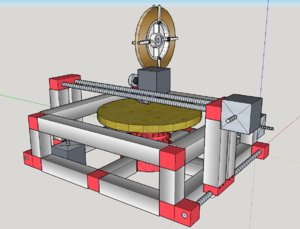
The goal of this project is to create a machine capable of manufacturing printed circuit boards (PCB) in an efficient and "green" way. There are many methods which could be used, but it was decided that the best method to use would be a unique copper tape applicator. Because of this, the machine is named Automated Copper Applicator for PCB Prototyping (ACAPP). ACAPP is still a work in progress, but all of the methodology is planned and is within the range of execution. In this report I will discuss how processes are selected, as well as the finer details of execution.
Method Selection
There are many methods for making PCBs, but among the most common are milling and photo-etching. Milling involves a sheet of copper glued to a sheet to epoxy-glass, where the unneeded copper material is milled away by a small radius end-mill. The second process mentioned, photo-etching, involves the same sheet of copper and epoxy-glass. In this process, a negative image of the circuit board is printed onto a sheet of transparent plastic, and is then taped to the copper sheet. They are then placed in Ferric Chloride, and light will cause a reaction, etching away unneeded copper areas. Both of these processes are "subtractive," meaning that there is a waste byproduct. Not to mention the hazards in storing or processing chemical waste from photo-etching.
It was decided to seek out a method which involved an additive process. The first method considered was a relatively new technology called "Conductive Ink." It is a silver compound in a paint marker like device. This method would prove very easy to implement on a standard gantry-styled machine, however, the ink is expensive, susceptible to smearing, and most importantly, the resistivity of the material is relatively high (up to 10 Ω per Cm). This is where the copper application comes into play. 3M makes thin copper tape used for electrically shielding devices and cables. The tape is flexible, and is pure copper, giving it a very low resistance (0.05 Ω per Cm). The tape can be applied in any shape or design within the limits of the materials width (3mm). This process is purely additive, efficient and inexpensive. Moreover, this method can be used to print on any material, from wood, to cardboard, cloth, or fiberglass.
Mechanical Hardware Design and Build
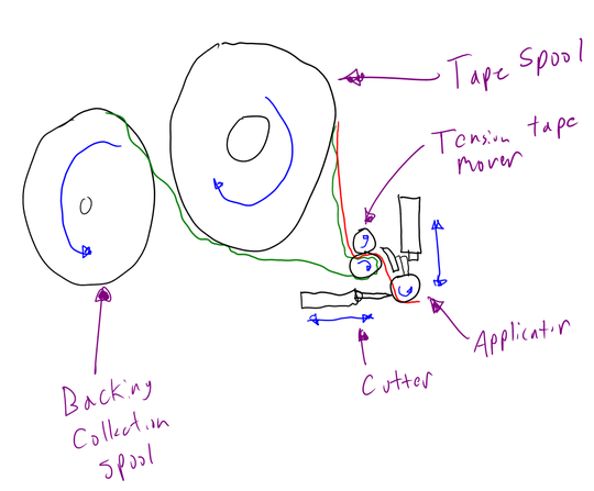
The first mechanical task undertook was a feasibility study to check if the copper application was possible. The applicator is the key part of this mechanical design, and the most complex. That said, its basic concepts can be viewed in the sketch in Figure 1. The basic process detailed in the sketch is this: Tape is spooled out and is gripped by a set of rubber wheels. On the outlet of the rubber wheels, the tape is peeled from it’s wax paper backing. The tape is deflected down to a tensioner which will roll the tape onto the PCB surface. A cutter is also positioned to end a line of tape.
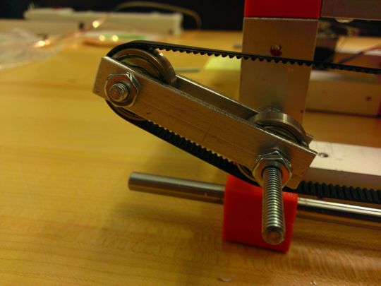
The tooling head must be on an automated positioning system. In this design, a gantry styled automaton system is designed. Construction materials chosen involve 1 inch square aluminum tubing, joined together by custom designed 3D printed parts. Tensioners are built from aluminum bar and and skate-board ball bearings, and can be viewed in Figure 3. Moving components are belt driven, and ride on linear bearings.
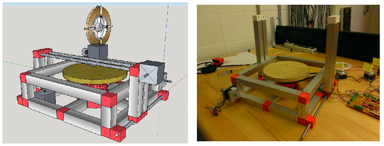
It is necessary for the printing table to rotate at least 90◦ , because the copper applicator is only capable of laying in one direction. The table is set on a ball bearing taken out of the differential of the formula race car. The table base is designed such that it can be rotated by a motor driven belt.
User Interface Software Design
Typically, PCBs are designed and exported as a file type called the Gerber file. It was decided that a Gerber file, though universally excepted by the industry, was too complex for this application. Instead, a software has been designed where custom PCB layouts can be designed, and saved in a simple .txt format. The data structure is simple: If you look at the PCB as a 2 dimensional plane, then a set of Cartesian coordinates can be applied. Each line in the design has both a start point and end point, of which can relate to the coordinate plane of the PCB. These coordinates are saved in an array, and eventually to a .txt file. The current interface design can be viewed in Figure 4.
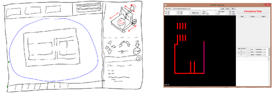
The software is designed in QTCreator, a free C++ development environment. It was chosen because of its QtPainter library, which is used to render the circuit board during the design phase, and its QtSerialPort library, which enables COM port access and control. The software is designed such that all necessary functions can be performed on a single screen. There is a function for designing the board, as well as saving and loading files. On the right side of the interface is a manual jog control, to move the machine for troubleshooting purposes. And finally there is a command console used for advanced debug.
The software will be designed to handle all translation from the designed coordinates to machine motions. This choice is significant, because computation will be done much quicker on the PC compared to on the microcontroller. The serial communication structure between the software and microcontroller are discussed in the next section.
System Firmware Design
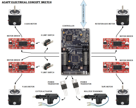
The firmware, by design, is relatively simple. Programmed on the Texas Instruments MSP-EXP432P401R microcontoller, its main function is to interpret serial signals, and relay information to motor drivers. The firmware is designed to interpret byte-wise serial data. The bytes received by the controller will carry data identifying the byte address, and then will either contain information about the step count or motor control information. In all control bytes, the 3 most significant bits are reserved for the address, which will allow for a maximum of 8 addressable bytes (2^3=8). The 5 bits left in the byte are used for data. For the step count byte in Figure 5, the 5 bits are part of a 15 bit signal, used for telling the motors how many steps they should make in their current configuration. Because the step data is a 15 bit number, it uses 3 serial bytes. The motor data byte in Figure 6 has 4 used data bits: MS1 and MS2 which are used to control the step size, DIR, which specifies rotational direction, and STP, which tells the motor if it is directed to move or not. Each motor operates off of a uniquely defined serial byte. These serial signals are received by the microcontroller, decoded, and then sent to their appropriate motor drivers or internal control variables.


Electrical Hardware Design and Build
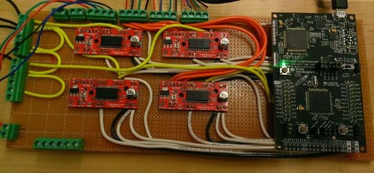
Taking a cue from industry standards the positioning motors were chosen to be stepper motors. This choice is because of their open loop controllability, as well as their availability and inexpensive price. The 4 positioning motors are each driven by a SparkFun EasyDriver. These driver boards receive binary data from the TI microcontroller. All of the control circuity is connected together on a piece of perf-board, and interfaces with motors through screw termination. The finished board can be seen in Figure 8.
Product Testing
ACAPP is not complete, however, multiple parts of the machine have been tested. After extensive debugging, the communication between user interface and microcontroller works flawlessly. The circuit board has also been tested, and appears to be free of problems. Motors were hooked to the board, and position control was tested and verified. At the time of writing, there are currently 2 axes finished and operational. The rotational axis of the table does have some issues that need to be remedied, namely belt slippage. This issues is temporarily fixed by tensioner bolstering using safety wire.
Plan to Finish Implementation
There is still a fair amount of work to be done to finish ACAPP. We are working to finish movement in all 3 axes first. This involves the completion of some mechanical build and testing. Once movement is working, there will be extensive testing for 3 dimensional position control. The final step is to build the copper applicator, and fixture it to the machine. Once again, the machine will have to go under extensive testing and calibration. Once this step is completed, the design will be assessed, and the continual refinement process will begin.
Conclusions
Building ACAPP has had a significant impact on my life. Since the design entails so many things from mechanical, to electrical, software, and manual construction, I have gained a strong consciousness of how an entire system works together. I have truly gained a strong understanding of system design. My C++ skills have increased, specifically working with bit-wise operations, because the programing was so logically intensive. I have also gained a proficiency in mechanical modeling; an ability I did not have going into this project. Another key thing learned during this project was market assessment, and benchmarking. I had to understand what was on the market for PCB manufacturing, what was good and bad about each option, and then try to improve on it. I feel that ACAPP has a true potential to become an actual consumer project, given enough refinement.
Contact details
Shane Oberloier
- Saginaw Valley State University Undergraduate Student
- Electrical and Computer Engineering Department
- Email: swoberlo@svsu.edu
- Site: voltfolio.com