Necessary tools for motor end assembly. Note that a stubby screwdriver will be required if a right angle driver is unavailable.
Tools
1.5mm hex key
2.5mm hex key
Precision knife
Small blade screwdriver
3mm drill bit and holder
8mm drill bit and holder
Right-angle or stubby screwdriver
Pliers
Note
The longer linking boards are used on the motor end. One of them has a slot cut in it.
Motors in the motor assembly have 35cm long wires. Do not mount the motor with the 70cm wires!
If your linking boards have any kind of etched design, ensure that the orientation is correct. The flanges for attaching the plywood rounds indicate the top of the printed ends.
Procedure
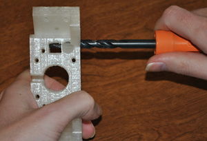
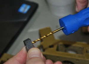
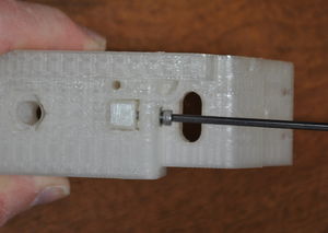
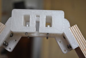
Prepping motor end.Bore through bar clamp with 3mm bit.Clean the motor ends with a sharp knife. Use 8mm and 3mm drill bits to ream all of the holes. Use a 3mm drill bit to bore the hole all the way through the bar clamps. Clear all protrusions from the linking board mount tabs, using the knife like scraper.
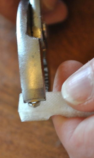
Squeezing nut into bar clamp.Put M3 nuts in the nut pockets in each of the six bar clamps. With pliers, squeeze the nuts all the way into the clamp until the face of the nut is flush with the surface of the clamp.
Starting from the side opposite the nut, check that an M3 screw will thread in each of the nuts after they have been inserted in the clamps.
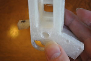
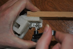
Inserting the bar clamp.Insert two bar clamps in each of the three motor ends. Insert the clamps so that the round pocket aligns with the guide rod pocket and the nut aligns with the hole going through the clamp pocket.
Fixing the bar clamp.Prepare six M3 x 16 screws with washers and put into the holes for the bar clamps. Just engage the threads, do not tighten the screw; guide rods will be inserted in a later step.
Make sure the long linking boards are being assembled with the motor ends! If linking boards (240mm × 42mm × 12mm plywood boards) do not have pilot holes drilled in them and you wish them to, follow directions here before proceeding.
Linking board attached to motor end.With the motor end laying with flanges down on the work surface, position a linking board so that its end is butted firmly against the end of the tab pocket. The board and motor end must be flat against the work surface. Start three #6 × 3/4” sheet metal screws into the tab and linking board but do not tighten them until the position of the board is checked – the board must be butted against the end of the motor mount tab so there is no gap between the plastic and wood and the board and motor end must lie flat on the work surface. Once in position, tighten the screws.
Repeat with another linking board on the other side of the motor end. A right-angle or stubby screwdriver will be required to engage some of the screws. Make sure that the last linking board is placed on the correct side of the motor end so that one of the motor ends does not end up being upside-down in the complete assembly.
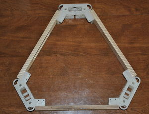
Motor ends and linking boards assembled.Continue with remaining linking board and other two motor ends. When complete, the whole assembly should lie flat on the work surface, flanges down, without rocking.
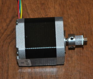
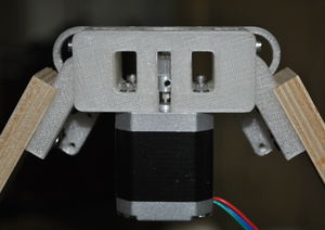
Motor with pulley.Put the pulley on the motor with at least one set screw lined up with the flat on the shaft. Fix it with the set screw(s). Leave a gap of about 5 mm between the pulley and motor.
Motor end with screws.Prepare twelve M3×12mm socket head cap screws each with an M3 washer. Stand the motor end assembly up on one linking board such that a motor end is facing upward. Carefully drop a screw with its washer into the motor mount holes.
Motor end with motor.Position the motor with the pulley facing up. The motor's wires should be exiting the motor towards one of the linking boards, not towards the top or bottom of the motor end. Start the screws into the motor but do not tighten until after all four screws have been started in threads.
Repeat with the remaining motors.
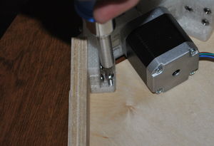
Attach the base to the motor end.Choose the side of the hexagonal wooden base you wish to be exposed and place that side down on the work surface. Align the motor end triangle, flanges down, over the plywood base and with the linking boards over the longer sides of the hexagonal base. Align the base and secure it with six #6 x 3/4" sheet metal screws through the holes nearest the center of the hexagonal base.
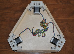
Nearly completed motor end assembly.Braid the motor wires.