#The actual end-effector is required for this procedure. If your printer is giving out successful prints, you can skip the calibration, but if you wanna re-calibrate, then start with the next step.
#If you own an Athena II, you would already be aware of the basic calibration process, irrespective of whether you built it yourself or not.
#If you own an Athena II, you would already be aware of the basic calibration process, irrespective of whether you built it yourself or not.
#But if you are new, please use this link. [http://www.appropedia.org/AthenaII_Franklin Go to section 2.3 on this page]
#But if you are new, please use this link. [https://www.appropedia.org/Athena_Board_Firmware Go to section 2.3 on this page]
#Your printer is now calibrated for the '''Hot End'''.
#Your printer is now calibrated for the '''Hot End'''.
#Now that you know the hot end effector calibration process, let's move on to calibrating the motor end effector.
#Now that you know the hot end effector calibration process, let's move on to calibrating the laser module end effector.
#Remove the mirror and attach a engravable surface like acrylic sheet or a thin wooden plank of appropriate dimensions that suit the printer.
#After attaching the laser end-effector, home the printer. The base of the laser module used was 63 mm below the end effector. So, enter 120 in the Z position box. This should bring the laser base to around 50 mm above the bed.
#Make sure the "Show Setup" checkbox is checked.
#Now, change the fan power to 0 from the Controls tab. This is an important step to switch OFF the laser.
#Scroll to bottom of the page to show the printer control buttons.
#Then, go to the Setup tab and find the Temps section. Change temp0 value to 0. It should be set to 50 by default. This is to use the laser as intended.
#Click the "Home" button.
#Now, place a thick (around 4-5mm) cardboard or a plywood sheet on the bed.
#Select the Z position text box (immediately below Z (mm)).
#Next step is to Switch ON the laser. Remain alert for this step, fumes may start coming up due to laser cutting through the material. Enter 5 in Fan power under the Controls tab. Watch for any fumes and change back to 0 if anything starts burning. If not, change the focus of the laser so that a dot appears on the sheet instead of a dispersed patch of light.
#Enter 10 in the Z position box (or leave it empty) and click Enter on the keyboard. The end effector should move down to approximately 10mm from the build platform.
#Change Fan power to 0 again and now you're ready for engraving.
#Now leaving the cursor in the Z position box, click the Page Down button so that the motor end effector is lowered step by step close to the mirror. Use Page Down or shift+down arrow as necessary to make sure the engravable surface is not damaged.
#When the engraving tool attached to motor, touches the engraving surface, type 0 in the Z position box. The engraving tool will be pressed hard against the engravable surface.
===Laser Engraving Plugin Download===
#We basically set the Z position to 0 for our motor end without damaging the engravable surface.
#Download Inkscape Gcode Generator Extension from Github here [https://github.com/305engineering/Inkscape].
#Now, please follow the steps 6 till 23 from section 2.3 Calibration on this page. [http://www.appropedia.org/AthenaII_Franklin Rest of Calibration] '''Note: where ever it is mentioned that paper should move freely with little resistance, make sure that it doesn't move at all.''' This will cause successful and clean engraving for us.
#Copy the files to the desired path and launch Inkscape.
#Now your printer is calibrated to accomodate the modified motor end effector.
#Note: you may need to repeat the steps above multiple times to achieve close to perfect calibration.
#I personally calibrated at-least 10 times.
===Inkscape Instructions===
===Inkscape Instructions===
#Change document settings in Inkscape to Width=70mm and Height=70mm. This is the maximum area we could engrave at once. This is because the Inkscape generates Gcodes only for what's on the workspace and nothing off the bed. But, a delta printer like AthenaII works on polar co-ordinates and has its 0,0 position at the center of the bed instead of the left lower corner for Cartesian printers.
#Import any image and resize according to the space avaiable. Then, "trace the bitmap" which can be found under Path menu. Press OK and then delete the image file that you imported.
#Next, go to the Extensions menu and find the 305 Engineering plugin and choose the option that comes up under it. In the dialog box that appears, you can provide the directory for the file. Also, change the resolution, engraving speed as required and press Apply and Close the dialog.
#Navigate to the directory where you just saved the file or else look for Quick Access in Windows Explorer. You will find a text file. Open this file and save it as a .gcode file. Now you're ready to Engrave!
#Since we are not using the hot end, set the printing temperature to 25 C or room temperature. You are eliminating the heating step.
# '''**Important**''' set all the print speeds to 8 mm/s or lower. This is the speed that I determined will be safe for connecting rods not to disconnect.
# Ignore all other paramters because you are not 3D-printing. Two most important things are step 1 and step 2.
#Scale your model down in the z direction if your slicer permits.
#Generally designing your engraving pattern with just 2mm in the z-direction will help.
#Make sure that the print speed on Franklin is 8mm/s or lower.
#Generate a gcode file to upload on Franklin and start engraving.
This Laser Engraver mod on the Athena II printer will allow you to engrave various designs on cardboard and/or wooden surfaces (acrylic material yet to be tested). You could also use the same setup for cutting sheets accurately enough upto 4mm. There are different steps involved to successfully install the DIY Laser Engraver on the Athena II. Detailed procedure and steps are listed below.
Card board and a small piece of wire (to mix and coat epoxy)
anywhere
Skills and Knowledge Necessary
Freecad or CAD experience to modify or re-design the end effector.
Knowledge of settings in Inkscape and settings in Franklin will help tweak few things.
3D Printing.
Assembly, Calibration and Inkscape Instructions
Assembly
Finish Printing the modified end effector from the above Printing step.
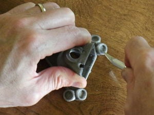
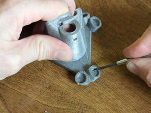
Steps 3 to 11 will be familiar to you if you built your Athena II yourself. If you bought an already built Athena II, follow the steps below carefully.The end effector depicted in the images is the original one. It is NOT our modified end effector. But the steps that involve cleaning magnet holes and inserting magnets work exactly the same.
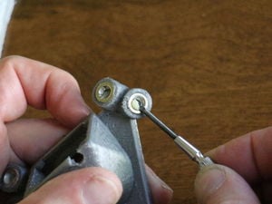
Cleaning magnet pocket sides with knife.Cleaning magnet pocket bottoms with screwdriver.Clean the magnet pocket sides with a sharp knife, Do not over dress the pockets - magnets should fit snugly!. Use a small flat blade screwdriver to clean protrusions off the bottoms of the pockets - it's important that the magnets seat fully in them. Be careful to not remove too much material as the magnets should fit snugly in them. Clean all of the pockets in the end effector.
The magnets come in pairs with pairs being identified as those attracted to each others' same face, that is the sides with the larger diameter recesses should attract each other. Magnets should be placed in the end effector such that nearest-neighbors attract rather than repel. Magnets may be placed in the carriages without regard for polarity.
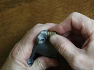
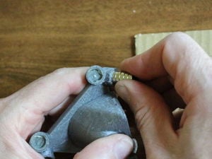
Magnets are placed in their pockets with the larger diameter opening facing outward. This is the surface that mates with the ball bearing on the end of a tie rod.
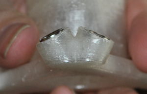
Test fitting magnets.Left: insufficiently cleaned; right: fully seating magnetTest fit the magnets in each of their pockets - they should fit snugly and all should fit flatly against the bottom of their pockets. Use the stack of magnets to insert and remove the end magnet during testing fitting. Do not let the magnets slam together!
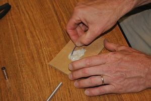
Mixing plastic epoxy.After ensuring the magnets fit properly in their pockets, remove them all from the pockets, keeping polarity in mind. Mix enough two part plastic epoxy to coat all the pockets in both end effector and carriages.
Applying epoxy to magnet pockets.Coat the interiors of all the magnet pockets with a thin layer of epoxy.
Inserting magnets into epoxy-coated pockets.Press the magnets into their pockets keeping in mind that the large diameter opening in the magnet points outward and the nearest neighbor magnets should attract each other in the end effector.
Fully seating magnets in their pockets.Press the magnets all the way into the pockets using a non-magnetic tool or fingers (the aluminum handle of the precision knife works nicely).
Cleaning epoxy off magnets.Clean epoxy out of magnet holes with the tip of a small screwdriver and paper towel. After curing, excess epoxy that remains on the face of the magnets can be removed with a sharp knife, but cleaning uncured epoxy is easier.
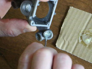
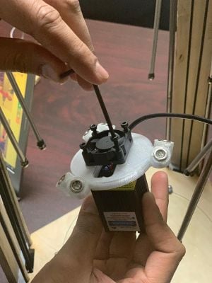
Fitting the Laser Module. Remove the small fan that came with the laser module. Place the fan on top side of the end effector and the laser on the bottom side. After aligning the holes, fix this sub-assembly using at least 2 2mm socket head bolts.
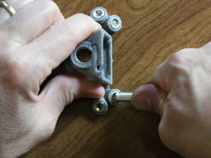
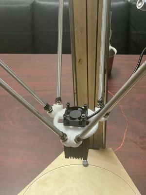
attached assembly to printer.You can now attach the whole assembly to the connecting rods of the Athena II printer.
Calibration
The actual end-effector is required for this procedure. If your printer is giving out successful prints, you can skip the calibration, but if you wanna re-calibrate, then start with the next step.
If you own an Athena II, you would already be aware of the basic calibration process, irrespective of whether you built it yourself or not.
Now that you know the hot end effector calibration process, let's move on to calibrating the laser module end effector.
After attaching the laser end-effector, home the printer. The base of the laser module used was 63 mm below the end effector. So, enter 120 in the Z position box. This should bring the laser base to around 50 mm above the bed.
Now, change the fan power to 0 from the Controls tab. This is an important step to switch OFF the laser.
Then, go to the Setup tab and find the Temps section. Change temp0 value to 0. It should be set to 50 by default. This is to use the laser as intended.
Now, place a thick (around 4-5mm) cardboard or a plywood sheet on the bed.
Next step is to Switch ON the laser. Remain alert for this step, fumes may start coming up due to laser cutting through the material. Enter 5 in Fan power under the Controls tab. Watch for any fumes and change back to 0 if anything starts burning. If not, change the focus of the laser so that a dot appears on the sheet instead of a dispersed patch of light.
Change Fan power to 0 again and now you're ready for engraving.
Laser Engraving Plugin Download
Download Inkscape Gcode Generator Extension from Github here [2].
Copy the files to the desired path and launch Inkscape.
Inkscape Instructions
Change document settings in Inkscape to Width=70mm and Height=70mm. This is the maximum area we could engrave at once. This is because the Inkscape generates Gcodes only for what's on the workspace and nothing off the bed. But, a delta printer like AthenaII works on polar co-ordinates and has its 0,0 position at the center of the bed instead of the left lower corner for Cartesian printers.
Import any image and resize according to the space avaiable. Then, "trace the bitmap" which can be found under Path menu. Press OK and then delete the image file that you imported.
Next, go to the Extensions menu and find the 305 Engineering plugin and choose the option that comes up under it. In the dialog box that appears, you can provide the directory for the file. Also, change the resolution, engraving speed as required and press Apply and Close the dialog.
Navigate to the directory where you just saved the file or else look for Quick Access in Windows Explorer. You will find a text file. Open this file and save it as a .gcode file. Now you're ready to Engrave!
Before starting to Engrave-
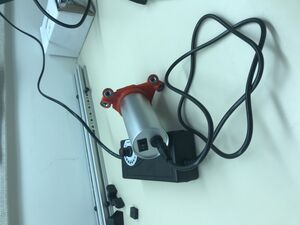
power cord/regulator attached Attach the power cord from an outlet to the motor.
You can control the rpm of the motor using the regulator.
You can improve the resolution of your engraving, using appropriate rpm.
Athena II Laser Engraver
Error in widget YouTube: Unable to load template 'wiki:YouTube'
Future Work
The calibration process is time consuming and frustrating. So, automatic calibration could be designed using auto bed leveling.
Since our engraving tool has to be in contact with our engravable surface, a spring mechanism can be integrated into the end effector - motor set up such that the tool is always in contact with the plexiglass/wood.