# [[File:Athena_fixed_belt_terminator0.JPG|thumb|right|Make sure there's enough belt to pass through the terminator '''large screw hole facing out'''.]]Hold the fixed (longer) belt terminator so that the larger screw hole faces you and the entry slot is facing down. Push the end of the belt passing over the idler through the slot in the belt terminator, wrap the belt around the rounded portion and then back into the slot. Push the belt into the slot such that it assumes the bend required to go back through the slot and pull the belt terminator tight.{{clear}}
# [[File:Athena_fixed_belt_terminator0.JPG|thumb|right|Make sure there's enough belt to pass through the terminator '''large screw hole facing out'''.]]Hold the fixed (longer) belt terminator so that the larger screw hole faces you and the entry slot is facing down. Push the end of the belt passing over the idler through the slot in the belt terminator, wrap the belt around the rounded portion and then back into the slot. Push the belt into the slot such that it assumes the bend required to go back through the slot and pull the belt terminator tight.{{clear}}
# Repeat the process with the free (short) belt terminator on the opposite end of the belt. Note that there is no special orientation required for the free belt terminator.
# Repeat the process with the free (short) belt terminator on the opposite end of the belt. Note that there is no special orientation required for the free belt terminator.
# [[File:Athena_check_gap_between_terminators.JPG|thumb|right|Adjust terminator positions until gap is about 25mm (1").]]Check the length of the gap between the two belt terminators. The gap should be about 25 mm (1") long. Adjust the position one of the terminators (choose the terminator that was easiest to install) to set the gap correctly.
# [[File:Athena_check_gap_between_terminators.JPG|thumb|right|Adjust terminator positions until gap is about 25mm (1").]]Check the length of the gap between the two belt terminators. The gap should be about 25 mm (1") long. Adjust the position of one of the terminators (choose the terminator that was easiest to install) to set the gap correctly.
# [[File:Athena_fix_belt_tails.JPG|thumb|right|Secure belt tails with small wire ties.]]Secure belt tails to the belt with small wire ties. This ensures that the belt doesn't slip when applying tension. Snip off the ends of the wire ties. Snip off the loose tails of the belt leaving about 2cm (1") above the wire tie.{{clear}}
# [[File:Athena_fix_belt_tails.JPG|thumb|right|Secure belt tails with small wire ties.]]Secure belt tails to the belt with small wire ties. This ensures that the belt doesn't slip when applying tension. Snip off the ends of the wire ties. Snip off the loose tails of the belt leaving about 2cm (1") above the wire tie.{{clear}}
# Install belts and terminators on the remaining two apexes.
# Install belts and terminators on the remaining two apexes.
DO NOT REAM the holes in the top of the carriages where the limit switch adjustment screws seat!
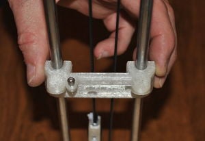
The belt terminators (assembly steps detailed below) have a narrow passage that the belt passes through twice - that passage needs to be cleaned with the precision knife. (During printing of the terminators, small protrusions form, making it very difficult to slide the belt through the passage.) Additional insurance against loss of belt tension is afforded by the small wire ties on the belt tails.
Procedure
Wipe down the guide rods with a clean, dry cloth or paper towel to remove any abrasive dust that may damage bearings.
Motor end on floor.Place the motor end assembly on the floor with the plywood base facing upwards.
Measure the depth of the guide rod pockets with a suitable tool.Transfer measurement to both ends of the guide rods. Drop a tool into one of the guide rod pockets and pinch between forefinger and thumb where the tool intersects the top of the pocket. Transfer the measurement to the ends of all guide rods, marking the approximate depth the rods should extend into the pockets.
Motor end on floor.Start the 8mm guide rods into the motor end clamps, rotate while pushing into the clamp. The rods should fit tightly in the clamps but not so tightly that beating on them is required to seat them; ream the 8mm guide rod holes in each motor end with an 8mm drill bit if necessary.
If considerable force is required to seat the guide rods:
DO NOT pound the rods into the pockets!
Ream the guide rod pockets with an 8mm drill bit taking care to not drill through the bottom of the pocket.
Try again seating the guide rods in their pockets.
Apply grease to interior of LM8UU bearings.Dip the back of the handle of the precision knife in grease and work the grease into the LM8UU bearings. This is an essential step - failure to adequately lubricate the bearings will cause premature failure of bearings and grooving of guide rods.
LM8UU bearings on guide rods.Slide lubricated LM8UU bearings onto the rods – one per rod. Repeatedly slide the bearings up and down the guide rod. The force required to move the bearing will decrease with continued movement.
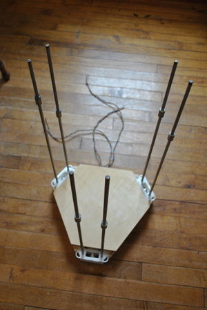
Push on the idler end.Align the guide rods with their clamps in the idler end lining up the limit switch wire exit with one of the vertexes having the slotted motor-side linking board between them. Carefully push the idler end assembly onto the guide rods until all are just started into their clamps.
Push the idler end onto the guide rods.Avoid fully seating just one set of rods in a single clamp - they may bind and it can be difficult to correct. Working in a circle around the idler end assembly, gently push on an idler end seating the entire idler end assembly on the guide rods little by little.
If significant force is required to seat the guide rods:
DO NOT pound the idler end onto the rods!
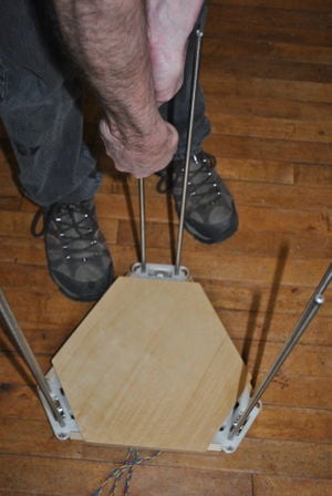
Working around the idler end, pull up on it while holding the motor end down with your feet; DO NOT pull just one of the idler ends off as other rods will become jammed, causing breakage.
Once the idler end is off, ream the guide rod pockets with an 8mm drill bit taking care to not drill through the bottom of the pocket.
Try again seating the idler end on the guide rods.
Check that the rods are fully seated in their pockets by noting position of the lines on the guide rods marking depth of pocket.Check the marks on the ends of the guide rods to insure that the guide rods are completely seated in their pockets. Take corrective action if they are not.
Use a vertical board to check printer height by noting gap between top donut and vertical board with the bottom of the vertical board flat against work surface.Check the printer height by standing a vertical board against each of the apexes noting that there should be about a 1mm-2mm gap between the plywood donut and the top of the vertical board:
If the gap is larger than about 2mm, the rods are not fully seated:
Carefully remove the idler end assembly by carefully pulling up on it while holding the motor end on the floor with your feet. Work around the idler end assembly pulling each idler end little by little.
Remove all the guide rods from their pockets.
Ream the guide rod pockets with an 8mm drill bit.
Clean out the pockets by turning the motor and idler end over and rapping on the back.
If there is no gap or the motor end sits off the floor with the vertical board in place:
Check the length of the vertical boards, they should be 605mm +/- 2mm. If boards are the correct length, continue, below:
Disassemble the printer per instructions, above. Remove all of the guide rods from their pockets.
With a flashlight, insure that the bottoms of the guide rod pockets were not drilled through. If they were, replace the damaged motor or idler end(s).
Check the length of the guide rods, they should be 590mm +/- 2mm.
Return the printer to the work surface with the idler end down.
Thread timing belt so ends are on the left side.Thread the belt through the right side of the idler box (side with the narrower gap between idler pulley and idler box) with the cogged side riding on the idler bearing. A flat screwdriver blade inserted at an angle into the box facilitates threading.
Loop belt and slide over pulley.Make a loop with the opposite end of the belt and slide it over the pulley on the motor taking care to not twist the belt. The ends of the belt should meet on your left side.
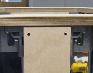
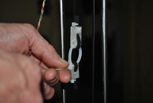
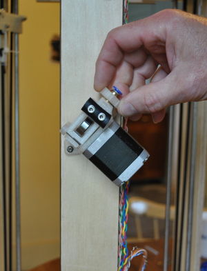
Make sure there's enough belt to pass through the terminator large screw hole facing out.Hold the fixed (longer) belt terminator so that the larger screw hole faces you and the entry slot is facing down. Push the end of the belt passing over the idler through the slot in the belt terminator, wrap the belt around the rounded portion and then back into the slot. Push the belt into the slot such that it assumes the bend required to go back through the slot and pull the belt terminator tight.
Repeat the process with the free (short) belt terminator on the opposite end of the belt. Note that there is no special orientation required for the free belt terminator.
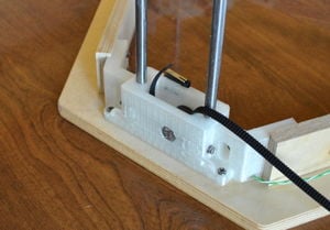
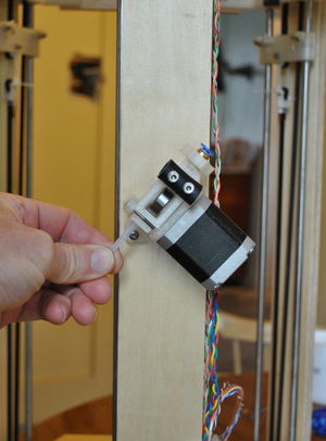
Adjust terminator positions until gap is about 25mm (1").Check the length of the gap between the two belt terminators. The gap should be about 25 mm (1") long. Adjust the position of one of the terminators (choose the terminator that was easiest to install) to set the gap correctly.
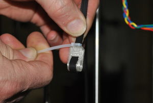
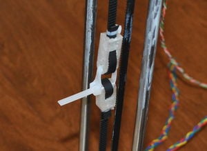
Secure belt tails with small wire ties.Secure belt tails to the belt with small wire ties. This ensures that the belt doesn't slip when applying tension. Snip off the ends of the wire ties. Snip off the loose tails of the belt leaving about 2cm (1") above the wire tie.
Install belts and terminators on the remaining two apexes.
Rotate the frame so that the motor end is on the work surface.
Large wire tie belt tensioner.Start a large wire tie through the fixed (long) belt terminator starting from the interior of the printer. Ensuring that the belt is not twisted, thread the end of the wire tie through the free (short) belt terminator's larger hole and secure the wire tie. Do not pull the wire tie tightly yet.
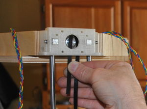
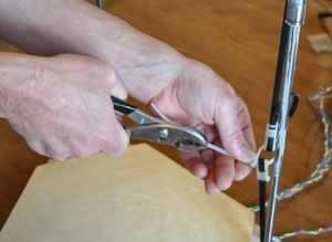
Pull the large wire tie tight to tension the belt.Rotate the printer so that the end of the wire tie is pointing towards you. Grip the wire tie clamp with your non-dominant hand and the end of the wire tie with a pair of pliers in your dominant hand. Pull firmly on the end of the wire tie, building tension in the timing belt. Pull reasonably hard but not so hard as to break the wire tie. Readjust the belt terminators and repeat. The belt should be tensioned such that it can be plucked like a guitar string and produce a deep bass tone.
Tensioned belt.Leave about 25mm (1") of the large wire tie. Snip off the end of the wore tie, leaving about 25mm (1") to grip if the belt requires future tensioning.
Repeat belt tensioning with remaining two apexes.
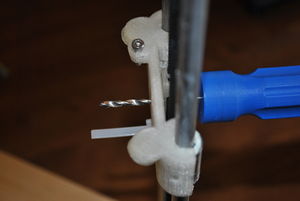
Ream limit switch screw holes in carriages.Plastiform threads in carriage limit switch screw pockets.Carefully ream the holes for the limit switch engagement screws in the carriages with the tip of the precision knife. Plastiform M3 x 12mm screws into the holes leaving the heads of the screws sitting proud of the top of the carriages.
Check that carriages don't drag on guide rods.Fit a carriage over a pair of guide rods, but not over the LM8UU bearings. Slide the carriage up and down the rods checking for clearance. If the carriage drags on the rods, open the guide rod passages with the precision knife. Repeat until the carriages ride on the guide rods with little force.
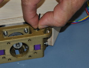
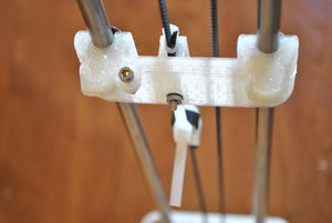
Reaming carriage belt mount hole in web.Orient a carriage over a pair of LM8UU bearings with the magnets facing the interior and angled towards the motor end. Snap the carriage on the LM8UU bearings with the magnets facing the interior and angled towards the motor end. Position the carriage and fixed belt terminator so that the holes in each align. Ream the hole with a 3mm drill bit.
Fix carriage to terminator with M3 x 16mm screw.Secure the fixed terminator to the carriage with an M3 x 16mm screw and nutwith a washer on the nut side only. The head of the screw should be fully seated in the recess in the belt terminator.
Fix the belt terminators on the remaining two apexes.
Prepare 12 M3 x 50mm screws with washers.
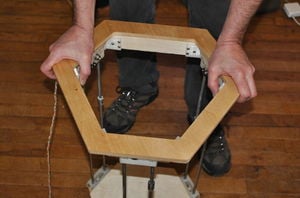
Be selective about which faces of the vertical boards are exposed (facing outward) and place M3 x 50mm screws in each of the four holes so that the screw heads or on the side you wish to have facing out.
Insert M3 x 50mm screws into idler end.Secure with nut and washer.Starting at the idler end, insert the M3 x 50 screws through their matching holes in the idler and motor ends. Secure the screws to the idler end with a washer and nut, but do not tighten them. Repeat with remaining two apexes and vertical boards.
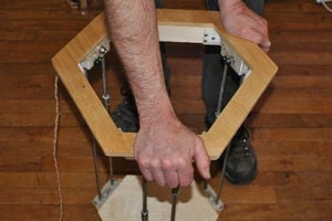
Tighten M3 x 50mm screws with nut only on motor ends.Invert the frame so that the motor end is facing up. Secure the M3 x 50mm screws with a nut only - there is not enough room for a washer. Tighten the screws on both the motor and idler ends. Repeat with remaining two apexes and vertical boards.
Tighten guide rod clamps on motor and idler ends.Tighten the M3 x 16mm screws securing the guide rods to the motor and idler ends.
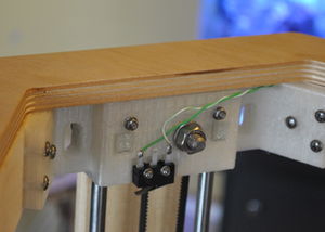
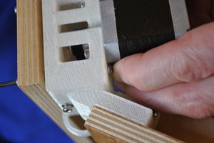
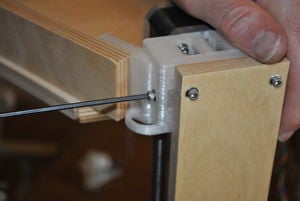
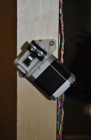
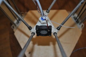
Attach the extruder drive to the vertical board that the limit switch wires run down.Return the printer to its upright position with motors down. Rotate the printer so that the vertical board with the limit switch wires is facing you. Mount the extruder drive with the larger exit hole angled upwards to the right (see photo) with two #6 x 1/2" sheet metal screws and positioned just above the mid point of the vertical board. The drive should be angled with the motor down to the right as shown in the photo. Braid the extruder drive motor wires.
Thread the quick connect on the extruder drive outlet.Locate the printed quick connect thumb screw and remaining quick connect fitting (the one with the smaller diameter hole) and fit the thumbscrew onto the quick connect fitting. Taking care to insure that the quick connect threads are aligned with the extruder drive outlet, thread the quick connect onto the extruder drive.
Push the PTFE inlet tube into the extruder drive inlet port.Push the short piece of PTFE tubing into the hole in the inlet port of the extruder drive. (This inlet tube facilitates insertion of filament while printing.)
Apply a small amount of grease to the ball bearings on the ends of the connecting rods.Engage ball bearings in carriage magnets.Push all of the carriages towards the top of the printer. Apply a small amount of grease to the ball bearings on the ends of the connecting rods and engage one rod with each of the magnets in the carriages.
Attach the end effector.Attach the end effector to the opposite ends of the connecting rods insuring that the tie rods are parallel.
Insert the Bowden sheath.Insert the loose end of the Bowden sheath (PTFE tubing attached to end effector) into the quick connect on the extruder drive.
Braid and secure wires to Bowden sheath.Braid the three sets of wires exiting the end effector (wrap the two smaller wires in opposing directions around the larger wires) and fix to the Bowden sheath with small wire ties. Do not braid the wires the entire length - leave the last 20cm (~8") unbraided to facilitate inserting the wires through the motor end wire passage in a later step. Do not over tighten the wire ties to avoid constricting filament inside the sheath. Snip off the tails from the wire ties.
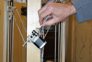
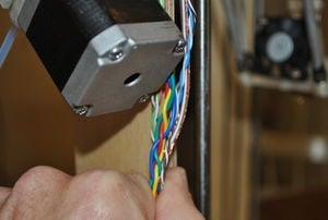
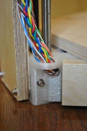
Bring wires together at base of extruder drive motor.Carefully feed wires through the guide and hole in motor end.Wires from the limit switches, extruder drive motor and end effector should all meet at the bottom of the extruder drive motor. Gather them neatly together and then carefully feed them through the wire guide and hole in the motor end directly below the extruder drive motor. Carefully pull the wires taught along the edge of the vertical board. Inverting the printer so the motor end is up eases this process.
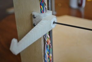
Mount the spool holder midway between the extruder drive and bottom of the vertical board. The spool holder doubles as a wire management device. Press it onto the vertical board with all of the wires between it and the edge of the vertical board. Mount the spool holder pivot to the vertical board midway between the extruder drive and bottom of the printer with two #6 x 1/2" sheet metal screws.
Mount the spool arm to the pivot.Locate the conical spool arm retainer and pass an M3 x 12mm socket head cap screw through it. Place the spool arm on the pivot with the arm pointing outward and tighten the screw and retainer to the pivot.
Frame complete.
(Note that the picture shows the build platform mounted; that should not be done until after completing the wiring.)