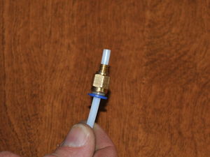
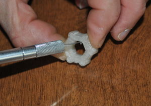
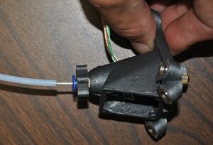
#* [[File:athena_check_quickconnect.JPG|thumb|right|Insure that the sheath fits through the reamed quick connect.]]Push one end of the sheath (PTFE tubing) into the reamed quick connector (the one with the larger hole in it) and ensure that it passes all the way through the connector. It should fit snugly but not require much force to insert.{{clear}}
#* [[File:athena_check_quickconnect.JPG|thumb|right|Insure that the sheath fits through the reamed quick connect.]]Push one end of the sheath (PTFE tubing) into the reamed quick connector (the one with the larger hole in it) and ensure that it passes all the way through the connector. It should fit snugly but not require much force to insert.{{clear}}
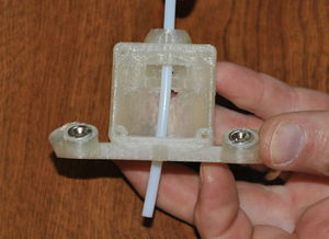
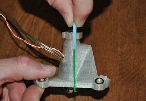
#* [[File:athena_check_effector_clearance.JPG|thumb|right|Insure that the sheath fits through the passage in the end effector.]]Check that the Bowden sheath will pass through the hole in the top of the end effector. Ream the hole using a 3mm drill bit like a file if there is any restriction.{{clear}}
#* [[File:athena_check_effector_clearance.JPG|thumb|right|Insure that the sheath fits through the passage in the end effector.]] '''(Skip if Hexagon hot end is used.)''' Check that the Bowden sheath will pass through the hole in the top of the end effector. Ream the hole using a 3mm drill bit like a file if there is any restriction.{{clear}}
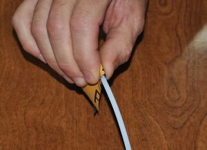
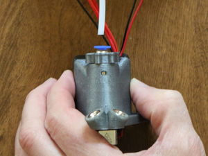
#* [[File:athena_check_hotend_clearance.JPG|thumb|right|Insure that the sheath can be inserted in hot end.]][[File:athena_taper_Bowden_sheath.JPG|thumb|right|Taper the last 10mm with sand paper.]]Check the clearance of the Bowden sheath in the hot end entry. It should extend into the hot end about 6mm (1/4") and it should fully seat without meeting any resistance. If resistance is met, use a piece of sand paper to remove material from the last 10mm of the Bowden sheath, forming a taper that easily and fully slides into the hot end.{{clear}}
#* [[File:athena_check_hotend_clearance.JPG|thumb|right|Insure that the sheath can be inserted in hot end.]][[File:athena_taper_Bowden_sheath.JPG|thumb|right|Taper the last 10mm with sand paper.]]'''(Skip if Hexagon hot end is used.)'''Check the clearance of the Bowden sheath in the hot end entry. It should extend into the hot end about 6mm (1/4") and it should fully seat without meeting any resistance. If resistance is met, use a piece of sand paper to remove material from the last 10mm of the Bowden sheath, forming a taper that easily and fully slides into the hot end.{{clear}}
#* '''Failure to complete the above will cause frustrating and time consuming problems later in assembly and during printing!'''
#* '''Failure to complete the above will cause frustrating and time consuming problems later in assembly and during printing!'''
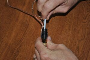
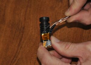
# [[File:athena_hot_end_wires.JPG|thumb|right|Bring the wires together on one side of the hot end.]] Bring the thermistor and resistor wires towards one side of the hot end. This side will face the back of the end effector where the wire exit passage is located.{{clear}}
# [[File:athena_hot_end_wires.JPG|thumb|right|Bring the wires together on one side of the hot end.]] Bring the thermistor and resistor wires towards one side of the hot end. This side will face the back of the end effector where the wire exit passage is located.{{clear}}
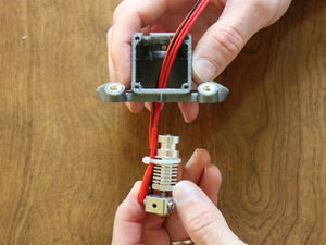
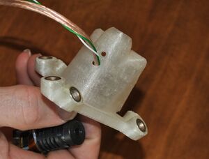
#[[File:athena_feed_effector_wires.JPG|thumb|right|Feed wires through wire passage.]][[File:athena_feed_effector_wires1.JPG|thumb|right|Note wires are aligned with back of end effector.]]Feed the wires through the large opening in the base of the effector and push it through the hole in the back of the effector so that it extends out the top of the effector. Remove any twist in the conductor. Pull the conductor through the top of the effector until the hot end is partially within the effector.{{clear}}
#[[File:athena_feed_effector_wires.JPG|thumb|right|Feed wires through wire passage.]][[File:athena_feed_effector_wires1.JPG|thumb|right|Note wires are aligned with back of end effector.]]'''(The Hexagon version has a wire passage at the top, left of the fan mount. Clean that passage with a knife and pass the wires through it.)''' Feed the wires through the large opening in the base of the effector and push it through the hole in the back of the effector so that it extends out the top of the effector. Remove any twist in the conductor. Pull the conductor through the top of the effector until the hot end is partially within the effector.{{clear}}
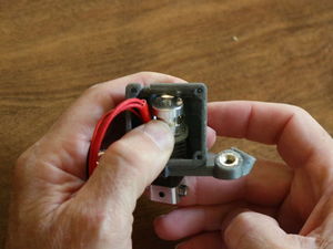
# [[File:athena_hotend_aligning.JPG|thumb|right|Aligning hot end with slot.]][[File:athena_hotend_insertion.JPG|thumb|right|Pressing hot end into slot.]]Carefully pull the conductors from the top of the effector while angling the slotted end of the hot end out the fan opening:
# [[File:athena_hotend_aligning.JPG|thumb|right|Aligning hot end with slot.]][[File:athena_hotend_insertion.JPG|thumb|right|Pressing hot end into slot.]]Carefully pull the conductors from the top of the effector while angling the slotted end of the hot end out the fan opening:
#* The hot end should be oriented with the wires facing the exit passage in the back of the end effector.
#* The hot end should be oriented with the wires facing the exit passage in the back of the end effector.
Line 67:
Line 66:
#* Check that the wires are not pinched between the hot end and the end effector as they will make it impossible to fully seat the hot end.{{clear}}
#* Check that the wires are not pinched between the hot end and the end effector as they will make it impossible to fully seat the hot end.{{clear}}
# [[File:athena_hotend_inserted1.JPG|thumb|right|Hot end in place.]]The slot for the hot end is purposefully tight-fitting; considerable force maybe required to fully insert the hot end in the slot. Be careful to minimize straining the conductors while pushing the hot end into its slot.{{clear}}
# [[File:athena_hotend_inserted1.JPG|thumb|right|Hot end in place.]]The slot for the hot end is purposefully tight-fitting; considerable force maybe required to fully insert the hot end in the slot. Be careful to minimize straining the conductors while pushing the hot end into its slot.{{clear}}
# [[File:athena_hotend_wire_closeup.JPG|thumb|right|Wires should look like this and not bunched up and pinched.]]Look through the bottom of the end effector and note the condition of the wires. They should be neatly aligned with the passage and not bunched up, bent and pinched between the end effector and the hot end.{{clear}}
# [[File:athena_hotend_wire_closeup.JPG|thumb|right|Wires should look like this and not bunched up and pinched.]]'''(Skip if Hexagon hot end is used.)'''Look through the bottom of the end effector and note the condition of the wires. They should be neatly aligned with the passage and not bunched up, bent and pinched between the end effector and the hot end.{{clear}}
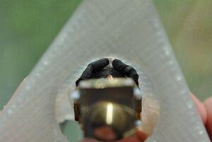
#[[File:athena_looking_through_hot_end.JPG|thumb|right|Look through top to check alignment.]]Check that the hot end is fully seated by looking through the top of the effector; the entry to the hot end should be centered under the Bowden sheath opening.{{clear}}
#[[File:athena_looking_through_hot_end.JPG|thumb|right|Look through top to check alignment.]]Check that the hot end is fully seated by looking through the top of the effector; the entry to the hot end should be centered under the Bowden sheath opening.{{clear}}
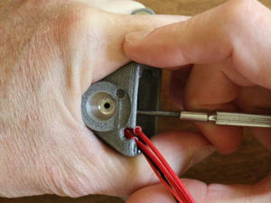
#[[File:athena_removing_hot_end.JPG|thumb|right|Note location of hole to push hot end out of effector.]]If the hot end refuses to fully seat in the slot, push the hot end out using a 2.5mm allen key in the hole provided (careful with conductors!), clean the slot again with a small blade screw driver and knife, carefully align the wires and try inserting the hot end again.{{clear}}
#[[File:athena_removing_hot_end.JPG|thumb|right|Note location of hole to push hot end out of effector.]]'''(Skip if Hexagon hot end is used.)'''If the hot end refuses to fully seat in the slot, push the hot end out using a 2.5mm allen key in the hole provided (careful with conductors!), clean the slot again with a small blade screw driver and knife, carefully align the wires and try inserting the hot end again.{{clear}}
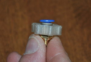
# [[File:athena_quick_connect_thumbscrew.JPG|thumb|right|Clean thumbscrew.]][[File:athena_quick_connect_thumbscrew1.JPG|thumb|right|Clean thumbscrew.]]Prep a thumbscrew attachment and press it onto the hex portion of the quick connect. Push it all the way to the plastic quick connect ring.{{clear}}
# [[File:athena_quick_connect_thumbscrew.JPG|thumb|right|Clean thumbscrew.]][[File:athena_quick_connect_thumbscrew1.JPG|thumb|right|Clean thumbscrew.]]Prep a thumbscrew attachment and press it onto the hex portion of the quick connect. Push it all the way to the plastic quick connect ring.{{clear}}
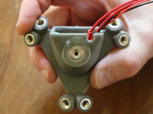
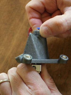
#[[File:athena_attach_effector_quickconnect.JPG|thumb|right|Thread on the reamed quick connector.]]Thread the reamed quick connect fitting into the top of the end effector. Carefully tighten in place.{{clear}}
#[[File:athena_attach_effector_quickconnect.JPG|thumb|right|Thread on the reamed quick connector.]]'''(The quick connect threads directly into the Hexagon hot end.)''' Thread the quick connect fitting into the top of the end effector. Carefully tighten in place.{{clear}}
#[[File:athena_mark_Bowden_depth.JPG|thumb|right|Mark depth on Bowden sheath.]]Use a 2.5mm allen wrench as a depth gauge - insert the allen wrench into the quick connect fitting until it rests on the bottom of the white insert in the hot end. Pinch the wrench with your forefinger and thumb to mark the location of the top of the quick connect. Transfer that depth to the Bowden sheath using a permanent marker. Be careful to not wipe the mark off the sheath.{{clear}}
#[[File:athena_mark_Bowden_depth.JPG|thumb|right|Mark depth on Bowden sheath.]]'''(Skip if Hexagon hot end is used.)'''Use a 2.5mm allen wrench as a depth gauge - insert the allen wrench into the quick connect fitting until it rests on the bottom of the white insert in the hot end. Pinch the wrench with your forefinger and thumb to mark the location of the top of the quick connect. Transfer that depth to the Bowden sheath using a permanent marker. Be careful to not wipe the mark off the sheath.{{clear}}
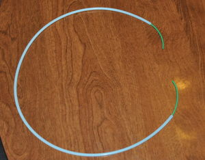
# [[File:athena_threading_filament_in_sheath.JPG|thumb|right|Thread filament through sheath.]]Push a 1m length of 1.75mm filament through the Bowden sheath so that filament extends out each end of the sheath.{{clear}}
# [[File:athena_threading_filament_in_sheath.JPG|thumb|right|Thread filament through sheath.]]Push a 1m length of 1.75mm filament through the Bowden sheath so that filament extends out each end of the sheath.{{clear}}
# [[File:athena_filament_as_guide.JPG|thumb|right|Feed filament into end effector and hot end.]]Push one end of the filament through the quick connect fitting and all the way down into the hot end. The filament will act as a guide while pushing the sheath into the quick connect and hot end.{{clear}}
# [[File:athena_filament_as_guide.JPG|thumb|right|Feed filament into end effector and hot end.]]Push one end of the filament through the quick connect fitting and all the way down into the hot end. The filament will act as a guide while pushing the sheath into the quick connect and hot end.{{clear}}
The newest design employs the all-metal Hexagon hot end and a modified end effector. We are working to update these instructions, but the changes are minor and much of what follows still applies.
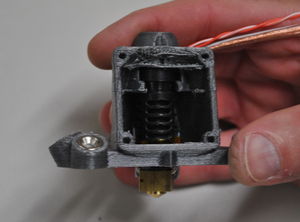
The end effector is the part that moves the extruder hot end around the build volume. The printed end effector is PLA, which if not cooled will soften under the heat produced by the hot end. A 40mm box fan cools the end effector, the heat sink on the hot end and also the part being printed. The fan must run when the hot end is heated!
The hot end must fit tightly in the end effector and getting it to seat can be difficult. Once seated, the hot end is kept from moving by the PTFE tubing which is pushed through the quick connect fitting and into the hot end.
The extruder is a Bowden cable design in which the filament is constrained in a low friction PTFE (teflon) tube. Filament is pushed on one side by the extruder drive and only permitted to exit out the orifice in the hot end. The Bowden sheath (the teflon tube) has a 2mm inside diameter that permits the 1.75mm filament to slide through easily. Teflon doesn't melt; chips left inside the tube will block the hot end nozzle and ruin your day.
Procedure
Check Bowden sheath clearances:
Insure that the sheath fits through the reamed quick connect.Push one end of the sheath (PTFE tubing) into the reamed quick connector (the one with the larger hole in it) and ensure that it passes all the way through the connector. It should fit snugly but not require much force to insert.
Insure that the sheath fits through the passage in the end effector.(Skip if Hexagon hot end is used.) Check that the Bowden sheath will pass through the hole in the top of the end effector. Ream the hole using a 3mm drill bit like a file if there is any restriction.
Insure that the sheath can be inserted in hot end.Taper the last 10mm with sand paper.(Skip if Hexagon hot end is used.)Check the clearance of the Bowden sheath in the hot end entry. It should extend into the hot end about 6mm (1/4") and it should fully seat without meeting any resistance. If resistance is met, use a piece of sand paper to remove material from the last 10mm of the Bowden sheath, forming a taper that easily and fully slides into the hot end.
Failure to complete the above will cause frustrating and time consuming problems later in assembly and during printing!
Bring the wires together on one side of the hot end. Bring the thermistor and resistor wires towards one side of the hot end. This side will face the back of the end effector where the wire exit passage is located.
Feed wires through wire passage.Note wires are aligned with back of end effector.(The Hexagon version has a wire passage at the top, left of the fan mount. Clean that passage with a knife and pass the wires through it.) Feed the wires through the large opening in the base of the effector and push it through the hole in the back of the effector so that it extends out the top of the effector. Remove any twist in the conductor. Pull the conductor through the top of the effector until the hot end is partially within the effector.
Aligning hot end with slot.Pressing hot end into slot.Carefully pull the conductors from the top of the effector while angling the slotted end of the hot end out the fan opening:
The hot end should be oriented with the wires facing the exit passage in the back of the end effector.
Align the top of the hot end with the slot in the end effector.
Push the hot end into the slot while simultaneously pulling up slack in the conductors from the other side.
Check that the wires are not pinched between the hot end and the end effector as they will make it impossible to fully seat the hot end.
Hot end in place.The slot for the hot end is purposefully tight-fitting; considerable force maybe required to fully insert the hot end in the slot. Be careful to minimize straining the conductors while pushing the hot end into its slot.
Wires should look like this and not bunched up and pinched.(Skip if Hexagon hot end is used.)Look through the bottom of the end effector and note the condition of the wires. They should be neatly aligned with the passage and not bunched up, bent and pinched between the end effector and the hot end.
Look through top to check alignment.Check that the hot end is fully seated by looking through the top of the effector; the entry to the hot end should be centered under the Bowden sheath opening.
Note location of hole to push hot end out of effector.(Skip if Hexagon hot end is used.)If the hot end refuses to fully seat in the slot, push the hot end out using a 2.5mm allen key in the hole provided (careful with conductors!), clean the slot again with a small blade screw driver and knife, carefully align the wires and try inserting the hot end again.
Clean thumbscrew.Clean thumbscrew.Prep a thumbscrew attachment and press it onto the hex portion of the quick connect. Push it all the way to the plastic quick connect ring.
Thread on the reamed quick connector.(The quick connect threads directly into the Hexagon hot end.) Thread the quick connect fitting into the top of the end effector. Carefully tighten in place.
File:Athena mark Bowden depth.JPGMark depth on Bowden sheath.(Skip if Hexagon hot end is used.)Use a 2.5mm allen wrench as a depth gauge - insert the allen wrench into the quick connect fitting until it rests on the bottom of the white insert in the hot end. Pinch the wrench with your forefinger and thumb to mark the location of the top of the quick connect. Transfer that depth to the Bowden sheath using a permanent marker. Be careful to not wipe the mark off the sheath.
Thread filament through sheath.Push a 1m length of 1.75mm filament through the Bowden sheath so that filament extends out each end of the sheath.
Feed filament into end effector and hot end.Push one end of the filament through the quick connect fitting and all the way down into the hot end. The filament will act as a guide while pushing the sheath into the quick connect and hot end.
Approximate length sheath and filament should be inserted.Feed filament into end effector and hot end. Push tubing fully into the hot end using a piece of sandpaper to grip the tubing.Push the Bowden sheath (PTFE tubing) into the quick connect fitting and all the way through it and into the hot end. Use a piece of sand paper to provide a better grip on the slick PTFE tubing. With sand paper it is possible to twist and push simultaneously, greatly improving the odds of fully inserting the sheath into the hot end. The tubing must be pushed fully into the hot end (to the previously applied mark) or filament will not feed properly.
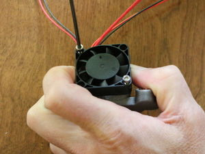
Attach fan to the end effector.Only two M3 x 12mm screws are required to affix the fan to the end effector: Place the fan over the opening with the wires exiting the fan towards the top of the effector and the fan spider (the part that usually has a sticker on it) facing the interior of the effector so that the fan is blowing air into the end effector (some fans have arrows embossed in the case indicating rotation and airflow direction). Align the fan's mounting holes with the holes in the fan opening and plastiform M3 x 12mm screws into opposite corners of the fan.
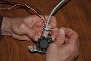
Feed filament into end effector and hot end.Secure the fan, thermistor and heating resistor wires to the Bowden sheath with a small wire tie immediately above the Bowden sheath opening.


