# Connect an Ethernet cable from your computer to the port on the Athena Board. Optionally, [[AthenaII_Wireless_Setup|set up the wireless connection at this point.]]
# Connect an Ethernet cable from your computer to the port on the Athena Board. Optionally, [[AthenaII_Wireless_Setup|set up the wireless connection at this point.]] If wireless is used, the IP address used to connect will be different.
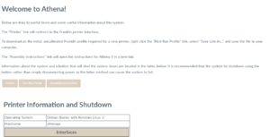
# [[File:Athena_board_homepage.png|thumb|right|Athena Board home page.]] Right click on http://192.168.76.2 and select "Open Link in New Tab". This is the Athena Board home page, containing a few useful links and the administration interface containing information and buttons for resetting Franklin, resetting the Athena Board and shutting the printer down.{{clear}}
# [[File:Athena_board_homepage.png|thumb|right|Athena Board home page.]] Right click on http://192.168.76.2 and select "Open Link in New Tab". This is the Athena Board home page, containing a few useful links and the administration interface containing information and buttons for resetting Franklin, resetting the Athena Board and shutting the printer down.{{clear}}
# Follow the instructions to download the initial Franklin profile..{{clear}}
# Follow the instructions to download the initial Franklin profile..{{clear}}
Plug the power supply into a wall outlet and plug the barrel connector into the socket on the Athena Board.
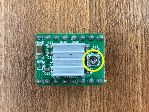
Note location of potentiometers.Locate the motor reference voltage adjustment potentiometers (see photo).
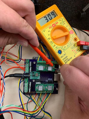
With the positive probe touching the screwdriver in the pot, and the negative probe touching the USB socket on the Orange Pi, adjust the U, V, W and extruder motor pots until 250 - 300mV is measured. With a small screwdriver and a voltmeter set for millivolt readings, adjust each of the small potentiometers on the motor controllers to produce a potential of 250 - 300 mV measured between ground (the USB socket can be used for ground) and the screwdriver used to adjust the potentiometer (see photo). Two sets of hands simplifies the task. Be careful to not short anything with the screw driver or voltmeter probe.
Franklin
Franklin is software designed to work with all 3-D personal manufacturing robots like Athena. It is both server and firmware, exposing all settings and controls on a web page served by the host computer, which in the case of Athena, is the Beaglebone Green.
Initial Setup
Connect an Ethernet cable from your computer to the port on the Athena Board. Optionally, set up the wireless connection at this point. If wireless is used, the IP address used to connect will be different.
Athena Board home page. Right click on http://192.168.76.2 and select "Open Link in New Tab". This is the Athena Board home page, containing a few useful links and the administration interface containing information and buttons for resetting Franklin, resetting the Athena Board and shutting the printer down.
Follow the instructions to download the initial Franklin profile..
Click on the Printer link to open the Franklin interface.
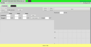
The Franklin interface. Note the two tabs - Control and Setup.
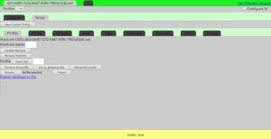
Activate setup tab. Activate the Setup tab to open the Setup interface. Be sure the Profile tab is selected.
Upload the initial Franklin profile. Click the 'Browse...' button and navigate to the location where the initial profile was saved and upload it by clicking the 'Upload' button after selecting it.
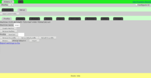
Name the printer. Name the printer by typing it in the 'Machine name' text box (e.g., 'Athena II'). Set the name by clicking the enter key.
Name the profile. Name the profile (e.g., 'Default') by typing it in the Profile text box. Set the profile name by clicking the 'Save (as)' button. Multiple profiles can be created and saved.
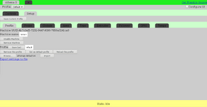
Click the "Set as Default Profile" button. Franklin will now load this profile when it is restarted by default. If after restarting Franklin the profile must be reloaded, it is because this step wasn't completed.
The firmware is now loaded, but the printer is uncalibrated and will not print properly. Complete calibration as described, below.
Changing Values in Franklin
Values in Franklin are presented with an input text box for making changes. The currently active value is shown next to the box.
Those text boxes permit entry of a value which is then set by pressing the "Enter" key on the keyboard. Values can also be changed by selecting a text box (left click on it) followed by pressing cursor up and down movement keys on the key board:
Page Up: increase value by 10
Page Down: Decrease value by 10
Up arrow: increase value by 1
Down arrow: decrease value by 1
Shift + Up arrow: increase value by 0.1
Shift + Down arrow: decrease value by 0.1
Math can also be performed in the text boxes; entering +1.5 (note plus sign) will add 1.5 to the value, entering +-1.5 (note the plus and the minus signs) will subtract 1.5 from the value.
All values of the same type can be changed at once by making the change in the maroon bar below the values.
Pressing enter on an empty box is the same as entering 0. Setting a value to something that Franklin cannot understand as a number sets it to NaN ("Not a Number"). For some settings, this is useful; for example, a temperature control is switched off that way.
The special values Infinity and -Infinity can also be entered (note the capital I), which is useful for some settings.
Calibration
NOTE
The current position of the end effector is shown just to the right of the text boxes for x, y, and z positions. The value in the text boxes themselves are what you entered - they may not match. To move the end effector to the desired position, enter the value and click the 'Enter' button.
Activate the 'Controls' tab.
Hover the mouse pointer over the 'Home' button. While watching the printer, click the button. If any of the carriages travel towards the motor ends, click the 'Abort' button. Activate the 'Setup' tab, then activate the 'Motors' tab. For the motors moving down rather than up, check the 'Inverted' box for those motors that were traveling the wrong direction. Click the 'Save Current Profile' button towards the top-left of the page.
In the 'Controls' tab, select the Z position text box (immediately below Z (mm)).
Enter 0 in the Z position box (or leave it empty) and click Enter on the keyboard. The end effector should move down so it is just off the build platform.
Place a piece of plain, white paper on the build platform under the hot end.
In the Setup>Motor tab, select the text box in the maroon row under Switch pos (mm) and increase the values until the paper is slightly pinched between the hot end and the build platform while the Z position is 0 - the paper should be mobile when pulled and pushed, but resistance should be felt.
In the 'Controls' tab, Move to Z = 50mm (select Z pos text box, enter 50, press Enter).
Select the Y position text box (immediately below Y (mm)) and enter a value of 100. Press Enter on the keyboard. The end effector should move near the vertex with the extruder drive mounted to it.
Move to Z = 0mm.
In the Setup>Motors tab, select the text box for the w motor switch position and change its value using the up and down arrow keys (with Shift as required) until the resistance on moving the paper is about the same as it was in the middle of the build platform.
In the Controls tab, move to Z = 50mm (select the Z pos text box, enter 50 and press Enter). The end effector will move 50mm off the build platform.
In the Setup>Type tab, select the Angle text box under the Delta section; enter 240 and press Enter. The end effector should move to the U vertex (counterclockwise from extruder drive vertex when looking down).
In the Controls tab, move to Z = 0mm.
In the Setup>Motors tab, adjust the u motor switch position until resistance is felt similar to that felt previously upon moving the paper.
In the Controls tab, move to Z = 50mm.
In the Setup>Type tab, set the angle to 120 degrees (Delta section, Angle position = 120 followed by Enter).
In the Controls tab, move to Z = 0mm.
In the Setup>Motors tab, adjust the v motor switch position until resistance is felt similar to that felt previously upon moving the paper.
In the Controls tab, home the printer.
In the Setup>Type tab, set the angle back to 0.
In the Controls tab, move to Z = 0mm.
In the Setup>Motors tab readjust all of the switch positions (in the Motor Settings area, select the text box in the maroon row, Switch Pos (mm) column) until the resistance upon moving the paper is the same as felt before.
In the Controls tab, move to Y = 100mm.
In the Setup>Type tab, adjust the radius of all motors at once (with the box in the maroon bar) until the resistance upon moving the paper is the same as felt before. (Decreasing the radius makes it more tight, increasing the radius makes it less tight.)
In the Setup>Profile tab, save the profile by clicking the Profile Save (as) button.
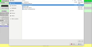
Save a backup of the profile to your computer: right-click the "Export settings to file" link and select "Save link as...". Save the file using a logical name in a logical location that you will remember. The backup can be reloaded by clicking the "Choose File" button just above "Export settings to file" followed by clicking the "Import" button. The backup can also be used as a starting point for calibration of a second Athena.
Proper operation of the fan on the end effector is very important as it keeps the plastic end effector cool. If it doesn't function correctly, the hot end will heat the plastic to the point that it deforms and the hot end becomes loose, resulting in very poor prints.
The Athena profile loaded into Franklin sets the temperature that the fan turns on at 50 degrees C. Verify this in the Temp Settings area under Show Settings (Fan Temp).
Set the temperature of the hot end to 60 degrees C in the Target temperature box immediately above the temperature chart by entering 60 and hitting enter.
Observe the fan at ensure that it turns on when the temperature exceeds 50 degrees C. If it does not, track down the problem. Be sure to check that the fan polarity is correct.
Shutting Down
Whenever the printer needs to be shutdown, navigate to the Athena Board home page (192.168.76.2) and click the 'Shutdown' button. This will shut the Orange Pi down in a controlled fashion, greatly reducing the chance of corrupting the file system.
To power it back up, the power must be disconnected and then reconnected.
Bookmark the Athena Board home page for easier access.


