The printable version is no longer supported and may have rendering errors. Please update your browser bookmarks and please use the default browser print function instead.
Snap carriages onto LM8UU bearings.Snap the carriages onto the LM8UU bearings with the magnets facing towards the printer's base. Secure the carriage to the fixed belt terminator with a M3 x 16 mm socket head cap screw. The head of the screw faces the exterior of the printer with the M3 nut and washer on the interior side against the carriage. Repeat with remaining two apexes.
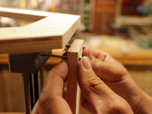
Attach vertical boards. Insert M3 x 50 mm socket head cap screws with M3 washers through the holes in a vertical board. Push the screws through their holes in the idler and motor ends. The holes will not align with the screws if the apex isn't properly assembled, e.g. the ends aren't fully pushed onto the guide rods. Secure the board in place with M3 nuts and M3 flat washers on the idler end and only nuts on the motor end (there is insufficient clearance for washer). Repeat with the remaining two apexes.
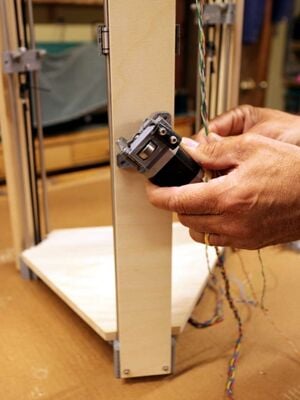
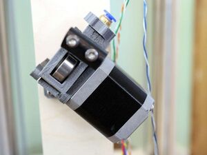
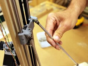
Attach the assembled extruder drive. On the apex having all the limit switch wires, position the extruder drive about half way up the vertical board and with the fuel hose angled up and to the right (see picture). Secure in place with two #6 x 1/2" sheet metal screws.
Attach quick-connect. With the precision knife, clean the thumbscrew so that it fits on the pneumatic quick-connect. Carefully thread the quick-connect on the outlet side (the side with the fuel hose) making sure it is threading squarely.
Place a small dab of grease on connecting rod ends. Place a small amount of grease on the ends of the connecting rods.
Engage connecting rod with carriage magnets. Engage the connecting rods with the magnets in the carriages.
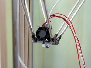
Attach the end effector. Engage the opposite end of the connecting rods with the magnets in the end effector. Note the orientation of the end effector - each pair of connecting rods must be parallel, otherwise the end effector is uncontrollable. If the end effector flops about and isn't rigid on the connecting rods, this requirement hasn't been met.
Attach the Bowden sheath. Push the 4mm PTFE tubing into the pneumatic quick-connect on the extruder drive. Tie the fan, thermistor and hot end wires to the Bowden sheath with three or four small wire ties. Do not over-tighten the wire ties as they can constrict the Bowden sheath and block the movement of filament.
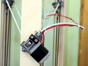
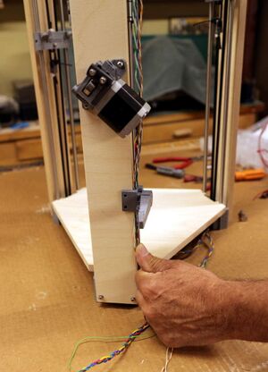
Attach the spool holder. Run all of the wires down the right side of the vertical board, pulling them towards the bottom of the frame. Secure the wires in place with the spool holder, placed about halfway between the extruder drive and the bottom of the printer. Secure the spool holder with two #6 x 1/2" sheet metal screws.
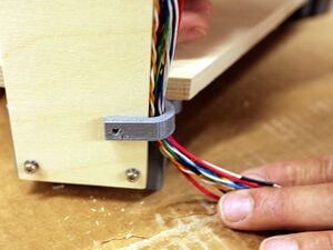
Secure wires at base of vertical board. With the wire retainer and a #6 x 1/2" sheet metal screw, secure all of the wires at the base of the vertical board.
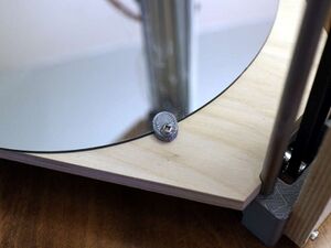
Secure the mirror to the base. The base is just large enough for the 10" mirror. Align the mirror and secure in place with the three printed glass hold downs and #6 x 1/2" sheet metal screws.


