No edit summary |
No edit summary |
||
| Line 1: | Line 1: | ||
== Overview == | == Overview of a Clarifier == | ||
{{Template:115inprogress|December 12, 2008}} | {{Template:115inprogress|December 12, 2008}} | ||
{{TOCright}} | {{TOCright}} | ||
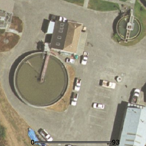
[[Image:Clarifier.png|thumb|left|Fig 1: Aerial view of Arcata Marsh clarifiers. The 60 ft tank can be seen on the left, and 26 ft tank on the right. (Source: Dustin Poppendieck)]] | [[Image:Clarifier.png|thumb|left|Fig 1: Aerial view of Arcata Marsh clarifiers. The 60 ft tank can be seen on the left, and 26 ft tank on the right. (Source: Dustin Poppendieck)]] A clarifier operates on the idea of slowing wastewater down so that suspended solids will settle out on the bottom of the tank. Wastewater is pumped to the clarifier after large solids and grit are removed. This removal occurs in the first two stages of wastewater treatment. In a clarifier the solids that settle to the bottom are called sludge. Less dense oils and solids called scum will float and settle on the top of the tank. The sludge and scum are then removed, and the water is pumped to oxidation ponds. After the entire process is completed the clarifier will have removed 40-60% of suspended solids<ref>http://ragsdaleassociates.com/WastewaterSystemOperatorsManual/Chapter%203%20-%20Primary%20Treatment.pdf</ref>. | ||
== Arcata == | == Arcata == | ||
The Arcata Wastewater Treatment Plant is equipped with two clarifiers. Figure 1 shows both of these clarifiers. The first is a 60 foot diameter tank that is used at all times. The second is a 26 foot diameter tank that provides support during frequent winter rains. The smaller clarifier can also be used when the main tank is | The Arcata Wastewater Treatment Plant is equipped with two clarifiers. Figure 1 shows both of these clarifiers. The first is a 60 foot diameter tank that is used at all times. The second is a 26 foot diameter tank that provides support during frequent winter rains. The smaller clarifier can also be used when the main tank is maintenanced<ref>Personal communication with Dave Couch</ref>. | ||
==== Center Fed Clarifiers ==== | ==== Center Fed Clarifiers ==== | ||
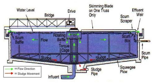
Both of the clarifiers at Arcata Marsh are center fed clarifiers<ref>http://www.cee.vt.edu/ewr/environmental/teach/wtprimer/sedimen/sedimen.html</ref>. Center fed clarifiers receive influent (wastewater entering the clarifer) from the bottom of the tank. From the bottom, the influent is pumped upward through the influent pipe in the center of the tank. This design is shown in Figure 2. | Both of the clarifiers at Arcata Marsh are center fed clarifiers<ref>http://www.cee.vt.edu/ewr/environmental/teach/wtprimer/sedimen/sedimen.html</ref>. Center fed clarifiers receive influent (wastewater entering the clarifer) from the bottom of the tank. From the bottom, the influent is pumped upward through the influent pipe in the center of the tank. This design is shown in Figure 2. | ||
| Line 25: | Line 25: | ||
== Settling and Removal Process == | == Settling and Removal Process == | ||
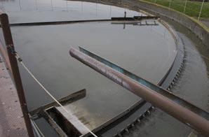
[[Image:Clarifier_skimer.jpg|thumb|left|Fig 4: The skimmer arm can be seen at the top of the photo. (Source: Dustin Popendieck)]] | [[Image:Clarifier_skimer.jpg|thumb|left|Fig 4: The skimmer arm can be seen at the top of the photo. (Source: Dustin Popendieck)]] | ||
==== Sludge ==== | ==== Sludge ==== | ||
The denser solids settle on the conical bottom of the tank in the form of sludge. A large rake with a squeegee like assembly rotates and moves the sludge towards a hopper at the bottom of the tank. The sludge is then pumped to the [[Arcata Marsh digester|digester]] for treatment. | The denser solids settle on the conical bottom of the tank in the form of sludge. A large rake with a squeegee like assembly rotates and moves the sludge towards a hopper at the bottom of the tank. The sludge is then pumped to the [[Arcata Marsh digester|digester]] for treatment. | ||
Revision as of 02:59, 13 December 2008
Overview of a Clarifier

A clarifier operates on the idea of slowing wastewater down so that suspended solids will settle out on the bottom of the tank. Wastewater is pumped to the clarifier after large solids and grit are removed. This removal occurs in the first two stages of wastewater treatment. In a clarifier the solids that settle to the bottom are called sludge. Less dense oils and solids called scum will float and settle on the top of the tank. The sludge and scum are then removed, and the water is pumped to oxidation ponds. After the entire process is completed the clarifier will have removed 40-60% of suspended solids[1].
Arcata
The Arcata Wastewater Treatment Plant is equipped with two clarifiers. Figure 1 shows both of these clarifiers. The first is a 60 foot diameter tank that is used at all times. The second is a 26 foot diameter tank that provides support during frequent winter rains. The smaller clarifier can also be used when the main tank is maintenanced[2].
Center Fed Clarifiers
Both of the clarifiers at Arcata Marsh are center fed clarifiers[3]. Center fed clarifiers receive influent (wastewater entering the clarifer) from the bottom of the tank. From the bottom, the influent is pumped upward through the influent pipe in the center of the tank. This design is shown in Figure 2.
Slowing the Water

The first task of the clarifier is to slow down the wastewater it receives from the headworks.
Water Entering
Water first enters the center of the tank through the influent pipe. A baffle slows down the velocity of the water to about 0.03-0.05 feet per second and directs the flow of water downward[4]. The baffle is a cylinder surrounding the end of the influent pipe.
Water Exiting

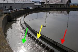
To ensure a consistent water flow the clarifier must also slow down the effluent (wastewater leaving the clarifier) evenly. The perimeter of the tank is designed to accomplish this. A series of v-notched weirs along the edge of the tank slow the water as it departs. In Figure 3 the weirs are pointed out. Once over the weirs the water enters the effluent launder (a channel around the outside of the clarfier). The wastewater can be seen flowing into the effluent launder in Figure 3.
Also displayed in Figure 3 is the inner baffle. The inner baffle rests behind and above the weirs. The inner baffle prevents floating solids from passing over into the effluent launder. From the effluent launder the water flows into a main collection trough and is pumped to the oxidation ponds via the effluent pipe.
Hydraulic Short Circuiting
If water does not flow evenly throughout the clarifier, the settling process will not occur evenly. This uneven flow is also known as hydraulic short-circuiting[5].
Settling and Removal Process

Sludge
The denser solids settle on the conical bottom of the tank in the form of sludge. A large rake with a squeegee like assembly rotates and moves the sludge towards a hopper at the bottom of the tank. The sludge is then pumped to the digester for treatment.
Scum
Lighter solids and oils rise to the top of the tank in the form of scum. Scum is removed from the tank by a rotating skimmer arm seen in Figure 4. The blade like arm collects the scum into a trough on the perimeter of the tank. Once the scum is collected it is transported to a landfill. Both the rakes and arm rotate together as they remove both sludge and scum from the tank.
Footnotes
- ↑ http://ragsdaleassociates.com/WastewaterSystemOperatorsManual/Chapter%203%20-%20Primary%20Treatment.pdf
- ↑ Personal communication with Dave Couch
- ↑ http://www.cee.vt.edu/ewr/environmental/teach/wtprimer/sedimen/sedimen.html
- ↑ http://ragsdaleassociates.com/WastewaterSystemOperatorsManual/Chapter%203%20-%20Primary%20Treatment.pdf
- ↑ http://www.environmentalleverage.com/Primary%20Clarifiers-%20Problem%20Areas.htm
Other References
- All photographs courtesy of Dr. Dustin Poppendieck, Assistant Professor of Environmental Resource Engineering, Humboldt State University.
- Principles of Environmental Engineering and Science/Davis and Masten. 2nd ed
<layout name="Project" />