Introduction

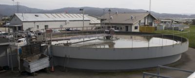
After passing through the Headworks where large solids, objects and particles are removed, the wastewater moves on to the primary clarifiers. Primary clarifiers, also known as sedimentation tanks, are used in wastewater treatment plants to remove solid materials from the water being processed. The Arcata Wastewater Treatment Plant uses two clarifiers, one 26ft diameter tank and one 60ft diameter tank Figure 1.
Clarifiers

Influent
Wastewater enters the clarifier through the influent well Figure 1 in the center of the tank. The influent well contains a series of baffles which reduce the velocity of the influent as it enters the clarifier; this is to prevent Short-Circuiting[2]. Short-Circuiting can occur when the water inside the clarifier gets disturbed and mixes, creating lower retention times and allowing solid waste to exit the clarifier along with the effluent.

Settling
Once the water enters the tank it velocity decreases, one it slows to solids begin to settle out of the water; the denser solids(sludge) settle to the bottom of the tank and less dense solids(scum) and oils float to the surface.
Scum
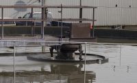
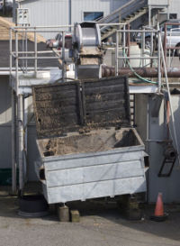
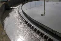
The floating scum is skimmed off of the surface by a large rotating arm called the surface skimmer Figure 3. Once collected by the surface skimmer the scum is deposited into the scum trough and is transported to a storage container alongside the clarifier Figure 4.

Sludge
The sludge on the bottom of the tank gets collected by rotating collector arms which moves the sludge to the center of the tank. Once the sludge collects at the bottom of the tank it gets pumped to the digester to be processed and converted into biogas.
Effluent

MORE TEXT WILL GO HERE
Links
References
- Davis, Mackenzie, and Susan Masten. Principles of Environmental Engineering and Science. McGraw Hill: New York, NY 2004.
- http://www.en.wikipedia.org/wiki/Sewage_treatment#Sedimentation
- http://www.gc3.com/techdb/manual/clartext.htm
- http://www.humboldt.edu/~ere_dept/marsh/flow2.html
- *http://www.humboldt.edu/~ere_dept/marsh/specs.html
- http://www.ragsdaleassociates.com/PrimaryTreatment.doc
- http://www.usace.army.mil/publications/armytm/tm5-814-3/chap11.pdf
- http://www.water.me.vccs.edu/courses/newENV110/Lesson5_print.htm