Picture of the parts required to assemble the micromanipulator.
3 pieces of OpenBeam, 75mm long.
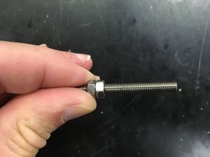
3 pieces M5 threaded rod, 65mm long.
3 M3 x 10mm flat head socket screws.
6 M3 x 6mm socket head cap screws.
4 M3 x 20mm flat head socket screws.
4 M3 x 25mm socket head cap screws.
15 M5 hex nuts.
6 MR105zz roller bearings (NOT PICTURED).
3 printed knobs.
3 printed straddle ends.
2 printed straddle carriages.
1 printed vertical straddle carriage.
Assembly
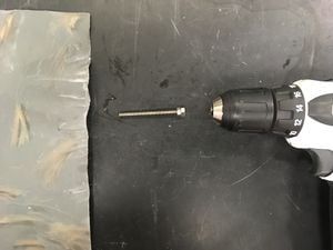
Remove burrs from threaded rod.Jam M5 nuts on one end of each of the threaded rods, chuck into a drill and remove burrs from the threads by rotating in #600 emory cloth or sandpaper.
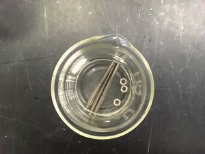
Thoroughly clean threaded rod and 3 nuts.Thoroughly clean the threaded rods and 3 nuts with alcohol in a sonicator for 5 minutes.
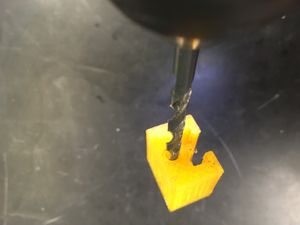
Run 2.5mm drill through captive nut retainer screw holes.Run a 2.5mm drill bit in the holes for the captive nut retainer screws.
Run a 5.5mm drill bit through leadscrew holes.Run a 5mm drill bit through all of the leadscrew holes in all the straddle ends and straddle carriages.
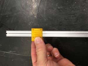
Slide carriage up and down a long piece of OpenBeam.The carriages should be very snug on the OpenBeam, but should slide reasonably easily. Run carriages back and forth on a long piece of OpenBeam until they slide easily.
Pull bearings into pockets with M5 screw.Line up the MR105zz bearings with their pockets in the straddle ends and run a M5 x 40mm screw them and the straddle end. Place the screw head on the side with the deeper pocket. Place a nut and washer on the M5 screw and tighten to pull in and align the bearings in the straddle end.
Pull captive nut into carriage.Use the same technique to pull the captive nuts into their pockets in the straddle carriages.
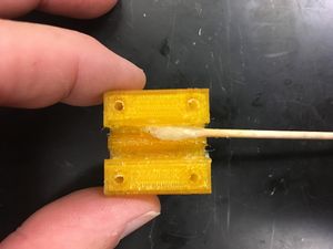
Thread in, but do not tighten the captive nut retainers screws.Thread the M5 x 6mm captive nut retainer screws into the straddle carriages. Do not tighten the screws!.
Tap threads into the carriage holes with the M3 tap or by "plastiforming" threads simply by running a screw into them.
Thread a single nut onto the lead screw.Thread a single nut onto each of the leadscrews.
Check position of nut.Ensure that enough thread extends from the back of the straddle end to engage two more nuts.
Start jam nut.Hold the properly positioned nut in place while starting the jam nut. Tighten the jam nut in place.
Check the position again.Again check that there is sufficient threaded rod extending from the end of the straddle end. Adjust if necessary.
Jam nut free end.Jam nut the free end of the threaded rod.
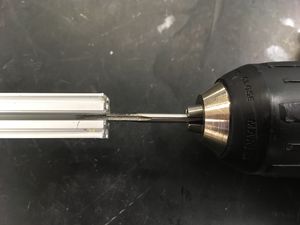
Tap OpenBeam end with M3 threads.Tap one end of each of the OpenBeam pieces with a M3 tap.
Screw OpenBeam in place.Gently tap the threaded end of a piece of OpenBeam into each of the straddle ends. Secure in place with a M3 x 10mm flat head socket screw.
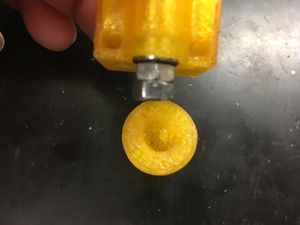
Align flats on outer nut and knob and tap into place.Align the flats on the jam nut and the pocket in a knob and gently tap the opposite end of the threaded rod to engage with the knob.
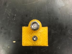
Install screws in one of the carriages. This is the Z-carriage.Countersink the four holes on the OpenBEam side of one of the carriages (not the vertical carriage). Insert the M3 x 20mm flat head socket screws into the countersunk holes. This is the Z-carriage.
Apply a small amount of grease to carriage interiors.Apply a light coating of grease to the interiors of the carriages.
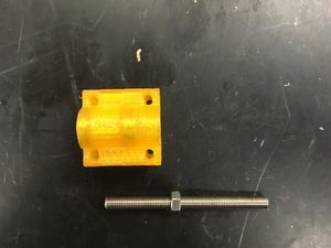
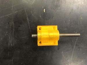
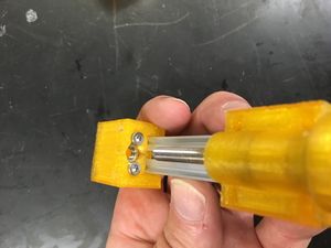
Slide carriages onto OpenBeam.Align the captive nut with the threaded rod and slide the carriages onto the pieces of OpenBeam.
Tighten retainer screws.Advance the carriage until the threaded rod is all the way through the carriage and then tighten the captive nut retainer screws.
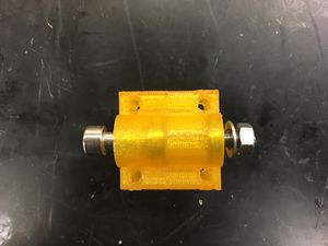
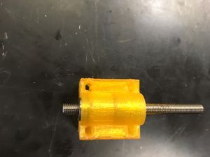
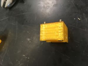
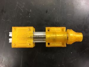
Assembled axis.A completely assembled axis should look as pictured.
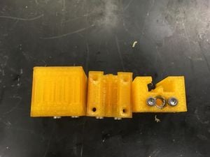
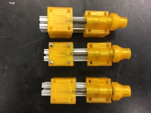
Completed set of axes.The completely assembled axes should look as pictured.
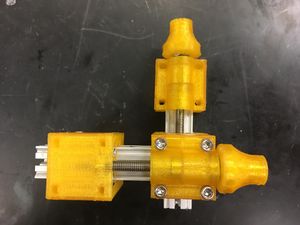
Connected X- and Y-axes.Connect the straddle end of the Y axis to the straddle carriage on the X-axis with the four M3 x 25mm socket head capo screws.
All axes assembled.Attach the Z-carriage to the Y-carriage with the four screws that were inserted into the Z-carriage. Tighten the screws step-wise, rotating through each screw to avoid breaking one of the carriages.