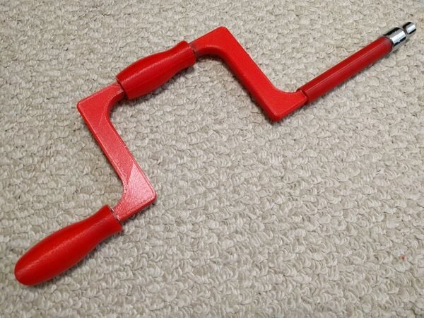
1/2" Drive Speed Brace / Speed Wrench
Project developed by Kerautio (talk) 21:21, 5 December 2016 (PST)
Template:Statusboxtop Template:Status-design Template:Status-prototype You can help Appropedia by contributing to the next step in this OSAT's status. Template:Boxbottom
Abstract
This project stems from the OXFAM equipment catalog and attempts to make a 3D printed version of a speed brace. The purpose of this tool is to quickly remove fasteners after they have been broken loose using a breaker bar or ratchet. This tool is meant to be used with 1/2" drive sockets.

Bill of Materials
Here is a bill of materials. Costs are based on a $20.00 / Kg of PLA filament price:
| Quantity | Part Name | Material (grams) | Cost ($) | Total ($) |
|---|---|---|---|---|
| 2 | Corner_Joined | 57.00 | 1.14 | 2.28 |
| 1 | Coupling | 21.00 | 0.42 | 0.42 |
| 1 | Coupling_Handle | 14.00 | 0.28 | 0.28 |
| 1 | Drive | 11.00 | 0.22 | 0.22 |
| 1 | Handle | 31.00 | 0.62 | 0.62 |
| 1 | Handle_End | 59.00 | 1.18 | 1.18 |
| 1 | Key_Long | 4.00 | 0.08 | 0.08 |
| 1 | Key_Short | 2.00 | 0.04 | 0.04 |
| Total Cost | $5.12 | |||
All STL files as well as source files can be found at youmagine.com [1]
Tools needed for fabrication of the OSAT
- MOST Delta RepRap or similar RepRap 3-D printer
- Hobby knife for print cleanup
- Hammer
Skills and Knowledge Necessary to Make the OSAT
Technical Specifications and Assembly Instructions
Recommended Print Settings
All STL files are orientated for printing. Print all objects according to the quantities listed in the BOM (Two "Joined_Corner" pieces are required).
- Layer Height: 0.25 mm
- Infill: 100%
- Support Material: None
- Shell Thickness: 2 lines
- Print Temp: 210 Degrees Celcius
- Print Time: Approx. 10 Hours
Part Preparation
- Clean all mating edges with a hobby knife. Be careful not to take too much off.
- Test fit parts while prepping the matting edges.
- If parts get stuck together use a 1/2" wrench and hammer to separate them.
- Parts should fit snugly together so that small taps with a hammer will seat the parts together.
Assembly
- Approximate Assembly Time: 30 Minutes
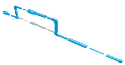
- After all parts are prepped lay them out as in the figure to the right.

- (Optional) Apply JB Weld or similar two part epoxy to all joints.
- Make sure the fat end of the handle is away from the drive end.
- Seat all parts with a hammer.
Common Problems and Solutions
- If 100% Infill does not provide enough strength there are a few options.
- Epoxy all joints
- Try an alternate print material
- Future consideration: may redesign with an overall larger cross section area.
Cost savings
Commercial Equivalent
A 1/2" drive speed brace can be purchased for $41.08 from [2]
Savings in Dollars
Given the print cost of $5.12 shown in the BOM and the cost of the commercial equivalent being $41.08, the savings are $41.08 - $5.12 = $35.96 Savings
Savings in Percent
Given the dollar savings of $35.96 calculated above and the cost of the commercial equivalent being $41.08, the percentage savings are ($35.96 / $41.08) *100 = 87.54 % Savings
References
- The following website was used to obtain dimensions for the 1/2" socket drive [1].
- ↑ . web page: Engineers Edge - Standard Square Drives for Socket Tools, ASA B5.38 (1958) Available: http://www.engineersedge.com/hardware/square-drive-tools.htm