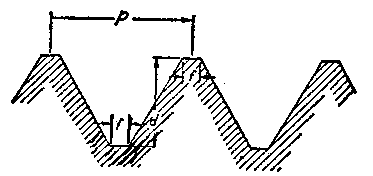
While screw-threads will vary, the American Standard is the one most frequently used in this country (USA) for all general work. The form of the thread is a triangle with an angle of 60 degrees between the sides. The top and bottom are flattened to a width of one-eighth the pitch; the depth is .649519 of the pitch. The pitch or rise of any thread is the distance the nut travels in one complete revolution. The American Standard Thread is shown in Fig. 1.
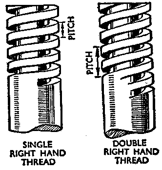
Threads may be left handed or right handed; a right-hand thread is one where the nut is screwed on the bolt by turning it to the right, or clockwise direction; the reverse applies to a left-hand thread. This difference in the direction of threads should be remembered, for it very often happens that the reason a nut or bolt cannot be loosened with a wrench is not because of rust but because the nut or bolt is being turned in the wrong direction – tightened rather than loosened.
Single and double threads are shown in Fig. 2. Multiple threads are necessary where a greater distance has to be traveled by the nut in one revolution than would be possible on a single thread.
Parts to be threaded together consist of an external thread and an internal thread, the external one being formed on the bolt and the internal one in the nut.
V type screw threads up to one inch in diameter can be cut by hand, but anything over this or other types of threads, are usually cut on a machine lathe.
The most satisfactory hand process consists of cutting the internal threads with a set of taps, and the external threads with a die held in a stock. Considering first the use of the taps, it is obvious that if a thread has to be cut on the inside of an object, such as a nut, a hole must be drilled first; since the diameter of all threads is measured to the outside, it follows that for, say, a 1-inch thread, the diameter of the hole must be 1 inch, less the depth of the thread on each side. This point is illustrated in Fig. 3.
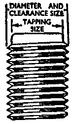
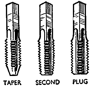
The diameter of the hole to be drilled is called the tapping size. A set of taps of the type used for cutting an internal thread is shown in Fig. 4. It will be noted that there are three taps in the set, all of the same maximum diameter. The taper tap is used first, and it will be seen that for some distance from its end there are no threads. This allows the tap to enter the hole and assists the worker in holding the tap in line with the hole, which is very important if accurate cuts are to be made. The tap-wrench fits the square end of the tap and forms a handle by means of which the tap may be turned gradually into the hole. If a tap is passed. through the hole, a complete thread is cut; but if the hole does not go through the metal, no thread is cut near the bottom of the hole. To make a clean thread in such a blind hole, it is necessary to follow with the second tap which, as can be seen, has only a few threads ground away at the bottom end. Finally, the plug or bottoming tap is used to complete the thread to the bottom of the blind hole.
When tapping a thread in thin metal, it is often difficult to keep the tap upright. A simple way to overcome this trouble is to place a nut of the same size and form as the thread to be cut on top of the hole and to press this firmly against the surface of the metal. The tap passes through the nut before entering the hole and is thereby supported.
Taps have to be extremely hard so that their threads may have as long a life as possible. In consequence, they are extremely brittle and are easily broken by the inexperienced user. Great care is required in use, especially with those of smaller diameter. Equal pressure must be applied with both hands to the tap-wrench; it is usual to press harder with the right hand, but this must be avoided. Incidentally, an excessively long tap-wrench increases the danger of unequal pressure and excessive force being applied.
Care should be taken not to turn the tap continuously; otherwise, the chips are not removed and the tap becomes wedged tightly in the hole. It should be turned forward about a quarter-turn, back a quarter-turn, forward a half-turn, and so on. The speed of tapping may be increased when the operator becomes used to the feel of the job and can judge from past experience just how much pressure to apply before the tap jams.
Should a tap break, it is possible to extract it by unscrewing with pliers if there is any part of the tap projecting, or by making a piece of steel with fingers to fit the flutes if the tap breaks off below the surface. In some cases it may be necessary to heat and soften the tap, then drill it out (as described for removing broken drills in Drilling metal).
To prevent the tap from overheating and losing its correct degree of hardness, oil should be applied freely during tapping.
Stocks and dies are used for cutting external threads. There are many different designs, the most common form being shown in Fig.5. The die takes the form of a hardened steel nut cut in two halves. Both parts have V-shaped grooves along their edges which fit over a corresponding projection on the side of the rectangular hole in the stock. Thus, the two halves are capable of sliding along and are adjusted to the correct size by means of a set screw. The dies are accurately fitted to the slides on the stock and are marked 1 and 2 to ensure correct position every time they are used.

A stock is usually designed to hold three sizes of dies (1/4 inch, 3/8 inch, and ½ inch, for example). For the next three sizes of dies a larger stock is used. A notch is cut out of the center of each half of the die, to allow for the disposal of the metal cut off. This also provides additional cutting edges and at the same time reduces friction and prevents binding. The smaller the amount of screw surface, the quicker the die will cut. On the other hand, a large serew surface helps to keep the die true and forms a better thread.
Before beginning to cut the thread with the stock and die, it is most important that the rod be of correct diameter. A perfect thread. may be cut on a rod which is either too small or too large, but in the former ease the nut will be loose end in the latter case will not fit.
The best plan, when both tapping and threading have to be done, is to tap the hole first, as this is of fixed size, and then cut the bolt-thread to fit. The rod should be slightly tapered near the end to give the die a start, and the dies can then be adjusted to fit the rod and the two halves tightened sufficiently to hold the stock and dies in position. Be sure to keep the stock at right angles to the rod which is to be threaded.
Turn the stock until a shallow thread of the required length has, been cut. Next, turn it back to the end and tighten the dies a little more; repeat the process until the thread has been cut to the correct depth. Test by using the nut previously tapped. If the nut will not go on when the thread has been fully cut on the rod, the rod is too large in diameter and part of the threads must be filed off before the dies are run down again. It is not wise to follow the practice of some metalworkers of using the dies to reduce the diameter of the rod. This will not only injure the die but it is almost certain to damage the threads or completely strip them. If the rod is of small diameter, it will probably be twisted off.
Using Dies. In using the die for threading iron or steel, the rod should be well lubricated with light machine oil to prevent the dies from becoming overheated. Also, it is important to keep the clearance notches free from waste metal.
After the dies have been run down the required length of thread, they must be turned back again without tightening, since they are designed for cutting the thread in one direction only.
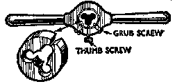
Fig. 5 shows another common type of stock and die suitable for cutting smaller sizes of threads. The stock is designed to take a greater number of dies than the larger type. The circular split die is held in the stock by three small set screws, and some slight adjustment in the diameter of the die is possible by tightening the center screw first. This opens the cut and so increases the effective diameter. This type of stock and dies is very often sold in sets and makes an extremely useful addition to the home workshop.
Iron Pipe. The most common threading job, as far as the home mechanic is concerned, is in connection with pipes for use in the plumbing system. The thread on pipes and pipe fittings is the American Standard. pipe thread having an angle of 60 degrees. Pipe thread is designed with a slight taper, the front being smaller in diameter than the end. This is done so that when the two pieces of pipe are screwed together the resulting joint will be water-tight. The fact remains that it is often impossible to get an absolutely watertight joint even when the threads are expertly cut and a pipe dope or compound is accordingly smeared on the external threads before joining. This compound will ensure the joint being tight.
The stock and dies used for pipe threading are similar in construction to those used for other machine threading jobs. It is impossible to cut and thread pipe properly unless it is gripped securely in a vise. Either use a pipe vise or a parallel-jaw vise fitted with pipe jaws (see Vises).
Before threading, the pipe, of course, must be cut to size. When measuring pipe some allowance must be made for the threaded portion at each end that will be screwed into the fitting. This amount will vary according to the diameter of the pipe. A good plan is to cut and thread the pipe so that it can be run right up to the recessed shoulder of the fitting.
Iron pipe is usually cut with a pipe cutter. A hacksaw may be used but it is almost impossible to make a perfectly straight cut with this tool, and if the end of the pipe is uneven it will throw the threads out of true.
The pipe cutter has small steel rollers and a cutting wheel. The space between the rollers and the cutting wheel can be regulated by turning the handle of the cutter.
Place the pipe to be cut in the vise and allow enough to extend beyond the bench so that it will be possible to revolve the pipe cutter around the pipe at the point marked for cutting. Slip the cutter over the pipe and adjust its position so that the cutting wheel is over the exact point to be cut. Turn the handle of the cutter so that the cutting wheel bites into the pipe just a little, then rotate the cutter around the pipe. Make sure that this first cut is accurate before continuing. After the first cut has been made, tighten the handle of the cutter and rotate it around the pipe again. Continue this process, tightening the cutter handle after each revolution. A few drops of machine oil on the cutting wheel will make the work easier. Needless to say, the success of this operation depends on having a sharp and accurate cutting wheel on the cutter.
After the pipe has been cut it is ready for threading, and this is done in the same manner as threading a rod. To get the die started squarely on the pipe, a bushing is used. Turn the stock slowly and apply oil to the die from time to time. If the threads are not straight or are not properly formed, it will be impossible to have a tight joint when the pipe is assembled. The burr on the inside of the pipe must now be removed, or it will reduce the flow of water through the pipe by a considerable amount. This job is done with a pipe reamer such as described earlier, under Reaming metal.