This special page shows all uploaded files.
| Date | Name | Thumbnail | Size | Description | Versions |
|---|---|---|---|---|---|
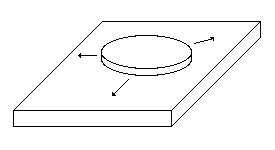
| 14:51, 28 November 2008 | MBEledgegrowth.png (file) |  |
1 KB | Diagram showing direction and shape of new layer growth in a slow deposition process, like molecular beam epitaxy. Circular growth is preferred. | 1 |
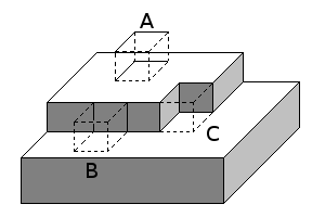
| 14:49, 28 November 2008 | MBElateralgrowth.png (file) |  |
3 KB | Atomic placement leading to lateral growth of a thin film. Atoms are represented by cubes. Atom A adds more broken bonds than Atom B when it is added to the system. Atom C adds no new broken bonds. Atoms are more likely to diffuse into positions B or | 1 |
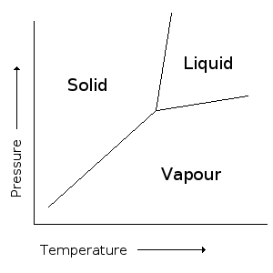
| 14:44, 28 November 2008 | MBEsinglephase.png (file) |  |
6 KB | Phase diagram for a single phase system. Source: Chris Cochrane (2008). Based on a diagram from Callister, W. Materials Science and Engineering: An Introduction, 7th edition. (2007) | 1 |
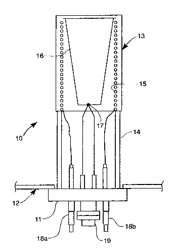
| 14:41, 28 November 2008 | MBEeffusioncell1.png (file) |  |
9 KB | Axial view of an effusion cell for use in MBE. Source: US Patent#5,540,780 (under Prior Art) (Haas, T. and Eyink, K., 1996) | 1 |
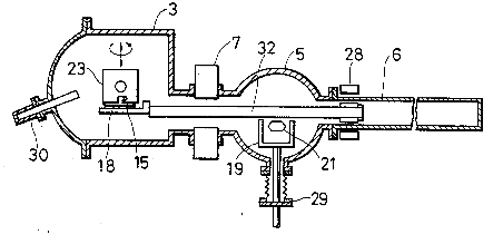
| 14:36, 28 November 2008 | MBEapparatus2.png (file) |  |
7 KB | Image of the apparatus used for molecular beam epitaxy. Source: US Patent#4,542,712 (Kazuo, et al., 1985) | 1 |
| 14:36, 28 November 2008 | MBEapparatus1.png (file) |  |
7 KB | Image of the apparatus used for molecular beam epitaxy. Source: US Patent#4,542,712 (Kazuo, et al., 1985) | 1 |