When creating projects and robots, no one likes to keep a cable connected at all times. It creates a feeling of something being unfinished, that your creation relies on something, that your precious peak of performance is limited by a simple length of a cable.
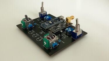
With that, I created a simple yet elegant solution to this problem, a universal remote control that can easily connect to any of my future projects. Bringing forward, the RC Ultimate. The RC Ultimate is the first design in a possible series of universal project controllers. Using the capabilities and size offered by the Arduino Nano, along with the range and ease of the nRF24L01, the RC Ultimate allows for easy implementation and set-up on the receiving end.
Circuit[edit | edit source]

The circuit for this project is quite simple. For collecting input, switches, buttons, potentiometers, and joysticks were connected. Each button and switch is connected to an individual pin on the Arduino Nano. As for the analog inputs, the potentiometers and joysticks had Analog pins dedicated to them to read the input. Past that, the nRF24L01 is wired to the Arduino Nano according to its libraries' documentations found on the Arduino Page on the SPI Library, and nRF24's RF24 library GitHub Repository.

As a power indicator, a 3mm Red LED was added with a 33k Ohms resistor. To power the whole controller, two CR2032 Lithium Coin batteries were wired in series to create 235mAh at a voltage of 6V. The batteries, after connecting to a power switch, are connected to the Arduino Nano's raw power pins which then get regulated to a 5V for the rest of the circuit to use.
The circuit was connected via THT on a 2-layer 1.6mm PCB designed on EasyEDA and ordered through JLCPCB.
See the circuit diagram and PCB design on EsayEDA.
Code[edit | edit source]
The RC Ulitmate utilizes the Arduino Nano as a microcontroller to read and send the collected values. Afterwards, the sent packets are picked up by another microcontroller over the 2.4 - 2.5 GHz ISM band using the nRF24L01 module. With that, there are two scripts written, one for the actual RC Ultimate as transmitter code, and the other as a demonstration of receiver code. Both scripts share a common Header File containing the structure of the packet being transmitted and received.
Both scripts make use of the SPI, nRF24L01, and RF24 libraries for the purpose of communicating with the nRF24L01 module. As well, all code is written using the PlatformIO IDE, allowing for easier writing and troubleshooting.
The Transmitter code simply configures the nRF24L01 module, declares the structure of the packet, reads the values of the hardware, assigns the values to the structure, and writes it to the preset address.
The Receiver code is made to create a demonstration of what the code on a receiving microcontroller can look like. At the moment, the demo code configures the nRF24L01 module, declares the structure of the packet, assigns the data read through the nRF24L01 to the declared structure, and prints the values over Serial.
View the code and its revisions on GitHub.
Design[edit | edit source]
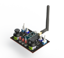
To manufacture the controller, a long printing time is required (and like anyone, I am impatient). With that, little time went into prototyping and the first iteration of CAD was used for the final product. Consequently, there are some flaws with the casing. Holding the controller seems rather cheap as it sits, to a certain degree, awkwardly in your hands. The curvature presented appears unnatural and fiddly. Lastly but most critically, to optimize printing times, the closure of the electronics consisted of a plate being able to unscrew at the surface. This, simply cutting corners and only designing for two screws means the plate can be lifted with a finger, bending the 3D print and damaging the design.
If moving forward with further RC controllers, more time will be dedicated towards prototyping. As well, the CAD will be created using SolidWorks Surface Modeling techniques to provide for more natural and appealing curvature.
Interactive CAD preview here.
Parts List[edit | edit source]
Parts needed include:
- x1 Custom RC Ultimate PCB
- x1 33k ohm Resistor
- x1 3mm Red LED
- x1 Arduino Nano
- x2 2-56 Machine Screws 1/4 in
- x2 3D Joysticks
- x2 MTS102 Toggle Switch
- x3 Gebildet 6×6×8mm Momentary Tactile Push Buttons
- x1 Slide Switch
- x1 NRF24L01+PA+LNA RF Transceiver Module
- x2 Potentiometers
- x1 CR2032 Coin Battery Holders
- x1 10uf Decoupling Capacitor
Inspiration[edit | edit source]
The main existence of this project came less from inspiration and more from a need. When creating or testing out projects, taking them wireless always posed a difficulty. Most commercial wireless solutions consisted of 2.4GHz Transmitters costing easily over 60$ CAD. With that, I created the remote to act as a cheap yet viable universal entity that can be connected to any project by just simply wiring an NRF24L01.
The following resources were used as a basis for the project:
Conclusion[edit | edit source]
To summarize, I would call the project a success. Although not fully satisfied with the design of the physical controller, it has set the groundwork for any similar projects that may come afterwards. For example, if needed, I would like to create a smaller version in the style of a Nintendo Switch Controller, with a single 2D joystick and a minimal amount of buttons.
The power supply being two unregulated batteries causes power spikes leading to connection loss when multiple states of buttons/switches are changed simultaneously. I would recommend using a mobile battery pack to power the controller or adding a battery regulator.