No higher resolution available.
Strawbridge_DIY_hydraulic_ram_pump.png (459 × 588 pixels, file size: 8 KB, MIME type: image/png)
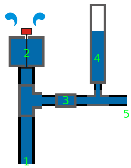
- 1: inlet
- 2: waste valve
- 3: delivery check valve
- 4: pressure vessel (optional)
- 5: outlet
Marked in grey are the different part of the hydraulic ram pump. Notice the two T-joints (one large one, and a small one); also notice the 2 different pipe diameters. Finally, notice that the pressure vessel is simply a pipe (same diameter as inlet pipe). Hoses can be connected to the inlet and outlet.
Image was based on http://commons.wikimedia.org/wiki/File:Hydraulic_Ram.gif and an image in the book "Practical self-sufficiency" by Dick and James Strawbridge
File history
Click on a date/time to view the file as it appeared at that time.
| Date/Time | Thumbnail | Dimensions | User | Comment | |
|---|---|---|---|---|---|
| current | 14:12, 20 March 2013 | | 459 × 588 (8 KB) | KVDP (talk | contribs) | *1: inlet *2: waste valve *3: delivery check valve *4: pressure vessel (optional) *5: outlet Marked in grey are the different part of the hydraulic ram pump. Notice the two T-joints (one large one, and a small one); also notice the 2 different pipe diame |
You cannot overwrite this file.
File usage
The following 2 pages use this file: