Original file (1,514 × 366 pixels, file size: 29 KB, MIME type: image/png)
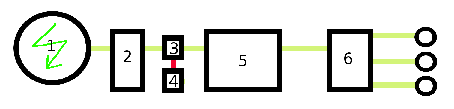
A schematic of a frequent used layout for small-scale renewable energy power plants; atleast those that use a permanent magnet alternator to generate the power and are off-grid (not grid-connected)
- 1: renewable energy power plant with permanent magnet alternator (PMA) to generate the power (often with a set of gears in between te PMA and the rotor so as to regulate the rotation speed to a suitable speed for the PMA to efficiently convert the power)
- 2: inverter
- 3: charge controller
- 4: dump load (takes excess energy -energy that can no longer be stored by the battery)
- 5: energy storage system (in this case, a deep-cycle electrochemical battery)
- 6: (pure sine) inverter for converting the power back to AC for use by AC appliances (ie conventional halogen lightbulbs, ...)
Note that as can be seen above, there are 2 power conversions (AC to DC and then DC to AC). This is done so as to be able to store the power in electrochemical batteries. It can be argued that it is more efficient to simply use a dynamo instead on the axle of the renewable energy power plant (as then 2 energy conversions -which may together account for 20% losses- are not needed). However, for example with wind turbines and waterwheels, the rotation speed is actually very slow and the PMA is one of the best options in this case (requires but 50 RPM and has 90% efficiency). As such, even with the conversion losses, it probably still more efficient than using a dynamo (dynamo's are much less efficient than alternators), and it also has the upside that electrochemical batteries can be used -which are very cheap compared to other energy storage systems and also more widely available-.[1]
References:
- ↑ Practical self-sufficiency by Dick and James Strawbridge
File history
Click on a date/time to view the file as it appeared at that time.
| Date/Time | Thumbnail | Dimensions | User | Comment | |
|---|---|---|---|---|---|
| current | 08:31, 19 March 2013 | 1,514 × 366 (29 KB) | KVDP (talk | contribs) | A schematic of a frequent used layout for small-scale renewable energy power plants; atleast those |
You cannot overwrite this file.
File usage
The following 2 pages use this file: