
Original file (1,002 × 1,736 pixels, file size: 498 KB, MIME type: image/png)
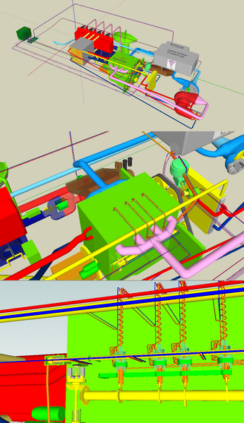
Snapshot of the 3D model of the AT IC motor 1 (Diesel version). This motor is designed specifically for running on 2nd generation biofuels. 2 setups are shown in this model. One of the models is fitted only with an internal combustion motor, the other is fitted with a internal combustion engine and an (alpha-type) Stirling motor (the efficiency of the first is about 30%, the other has a 70% efficiency). The first setup is intented for mobile applications (use in vehicles) whereas the second is intented for stationary applications. Both run on ethanol for starting and stopping, and on vegetable oil for general running (the bi-fuel system is needed as the engine first needs to be sufficiently hot before the viscous vegetable oil can be used). For the same reason, the fuel line between the vegetable oil tank and the engine is heated using electrical heater wires. Although electrical wires are generally not used for this (instead most systems rely on the heated coolant water), with the combined IC-Stirling setup, it does not create energy losses as the waste heat of the IC engine is allready used for the Stirling motor anyhow, so tapping into this waste heat for fuel line heating would create equally large losses, making the use of electrical wire heating equally efficient. Where the wire does not need to be heated; the diameter is enlarged, causing much less heat to be released (see http://www.engineeringexpert.net/Engineering-Expert-Witness-Blog/?p=3423 )
Note that no filter is present in the model. This is because a filter complicates the design considerably, and also forms a major bottleneck. As such, it is considered that the oil placed in the tank is allready very clean. A seperate filter unit can ratherbe used to filter the oil prior to introduction to the tank.
Regarding the differences between the Diesel engine assembly and the gasoline version assembly: first of all, there is no carburettor, in a Diesel engine. Instead, there is a governor which injects the fuel into the cylinders after that the cylinders have first been fueled with compressed air. The governor injects the fuel in the proper order (1-3-2-4), so no magneto is needed aswell. The reason why the compressed air is first introduced to the cylinder is because compressed air is hot, hence supplying the "spark" needed to combust the fuel/air mix. The compressed air is always introduced to the cylinders at full power (no waste gates are used after the turbocharger). The turbocharger is also fitted with a electrical starter motor to get it running even at engine startup (so even when there is no exhaust gas leaving the engine, normally powering the turbocharger). The use of the turbocharger (and the compression stroke of the piston) should be enough to combust the mixture, if it isn't then a additional air compressor (ie Roots blower) should be added.
It should also be noted that the governor is also capable of regulating the fuel amount injected to the cylinders. This is done trough the fuel rack, which is controlled by a carrier with flyweights, these being controlled by the rotation speed of the engine's axle. As the carrier moves up or down, it pushes or pulls oil into a chamber beneath it (using the pilot valve plunger), engaging the fuel rack, which rotates the sleeve on the jerk/helix pistons. See also http://www.splashmaritime.com.au/Marops/data/text/Med3tex/Engpropmed2.htm
There are also additional differences to the engine itself, ie ante-chambers are present (heated when cold at startup using glow plugs) and the Diesel engine version (compared to the gasoline engine version) only has 2 valves and 2 pipes connected to the cylinder, as opposed to 4 with the gasoline version. This is because more than 2 pipes/valves do not increase efficiency, but it does make the engine more complex/costly, so only 2 pipes/valves where used.
File history
Click on a date/time to view the file as it appeared at that time.
| Date/Time | Thumbnail | Dimensions | User | Comment | |
|---|---|---|---|---|---|
| current | 11:32, 11 September 2012 | | 1,002 × 1,736 (498 KB) | KVDP (talk | contribs) | Snapshot of the 3D model of the AT IC motor 1 (Diesel version). 2 setups are shown in this model. One of the models is fitted only with an internal combustion motor, the other is fitted with a internal combustion engine and an (alpha-type) Stirling motor |
You cannot overwrite this file.
File usage
There are no pages that use this file.