This page documents the final course project for the Spring 2021 ENGR 535 (Development Technology) course at Cal Poly Humboldt. Our team was tasked to design and deploy a stand-alone air monitoring system that can monitor the air quality in a location which has cellular connectivity and reasonable solar access, but without access to power and internet. Our project was deployed at the Blue Lake Rancheria in Humboldt County, CA.
This page includes a design and construction and user manual for our final product.
Bill of Materials[edit | edit source]
| Item | Amount | Cost per unit | Total |
|---|---|---|---|
| Sensor - PurpleAir PA-II [1] | 1 | USD 249.00 | USD 249.00 |
| Network - KuWfi GC111-L [2] | 1 | USD 89.99 | USD 89.99 |
| Storage - 12V 30Ah Lithium Iron Phosphate Battery [3] | 1 | USD 143.65 | USD 143.65 |
| Charge Controller - 20A Solar Charge Controller [4] | 1 | USD 17.99 | USD 17.99 |
| Power - 2x 40W Solar Panels (Free) | 1 | USD 0.00 | USD 0.00 |
| Enclosure - Weatherproof Junction Box [5] | 1 | USD 41.49 | USD 41.49 |
| Enclosure - Waterproof Cable Connectors [6] | 1 | USD 15.00 | USD 15.00 |
| Structure - Wooden Pallet (Free) | 1 | USD 0.00 | USD 0.00 |
| Network Plan - AT&T IoT LTE-M 1GB Plan | 1 | USD 22.00 | USD 22.00 |
| Grand total | USD 579.12EUR 498.04 <br />GBP 422.76 <br />CAD 718.11 <br />MXN 12,074.65 <br />INR 43,347.13 <br /> | ||
Wooden Mount[edit | edit source]
Components and Tools[edit | edit source]
- 1 (or two maybe) x wooden pallet
- 1 x pry bar
- ~10 1" nails
- ~20 x 3" wood screws
- ~50 x ½" wood screws
- ~20 x 1" wood screws
- 1 x 12" long metal plate
- 14 x Steel L Angles
- 1 x hand saw
- 1 x screwdriver or electric hand drill
- 1 x protractor or some kind of angle measuring tool
- 1 x hammer
Assembly[edit | edit source]

To build the wooden mounting structure, firstly get a wooden pallet that is in good condition (all or most of the cross boards are not cracked or broken) and has at least 8 or 9 cross boards (keep in mind that boards one and two are doubled, so this pallet had 9 cross boards in total). Mark the cross-boards numerically as shown in the attached figure. Next, carefully remove all the cross boards from the pallet with the help of a hammer and your pry bar. Make sure to wear safety gloves while doing the job to ensure your safety. Knock out the nails remaining in the boards when you can, otherwise hammer them down to avoid puncturing yourself during construction.

Keep the three pallet braces intact (board #3 that has three large spacing blocks), as one of these will be the central pillar of your wooden mount structure. To build the base of the mount, collect two cross boards (#1) and nail them together. Place the center pillar in the middle of the boards and screw the boards to the pillar from below with at least three (3) 3" wooden screws. Collect two more cross boards (#2), saw them in half, and set them perpendicular to the other double board lined up with the central pillar. Secure each leg of the base to the central pillar using two L brackets per leg, using 3" wooden screws for the top connection on the pillar, ½" wooden screws for both inside connections, and 1" wooden screws for the outside connections on each leg.

To add more stability to the structure, set the assembly on its side and screw the 10" straight bracket in the bottom of the center pillar (using 2 x 3" screws and 4 x 1" screws), making sure it is parallel to the free-standing legs.

After fixing the base mount on the center pillar, the base mount and center pillar sub-assembly are ready. Put the mount to the side to make more workspace for the next subassembly.

Next, you will build the panel mount wooden structure. Place the two panels next to each other, long side together, and place a wooden board (#5 from step 1) from the pallet between them. Measure the length of the two-panel widths plus the board's width and subtract from that 2X the width of the panel frame. Note the resulting length, and cut two boards (#4 from step 1) to this length.

Measure the width of the center pillar and place the two boards apart from each other at this width, centered on the wooden strip which you placed on the ground while taking measurements of solar panels as shown in Step 5. Secure them by using an L bracket outside the wooden strip. Flip the board over and screw in two 1" screws for each board for added more stability.

Now, cut two boards to just under the width of the solar panels (#6 in step 1). Screw both of them to either end of the longboards you initially placed on the ground. Make sure to leave an overhang at each end equal to the width of the panel frame as the panel frame will fit over these boards, and secure each corner with an L angle bracket on both sides.

Now, and cut ½" deep notches directly above and below the centerboard. Finally, secure the panel mount onto the central pillar at your desired angle with the help of your angle measuring device and 4 x 3" screws. For this project, we mounted the panel mount at an angle of 23 degrees with the help of an angle protractor.
Junction Box[edit | edit source]
Components and Tools[edit | edit source]
- 1 x (16" x12" x7") Electrical Junction Box
- 1 x 10A Charge Controller
- 1 x 12V 30Ah LFP Battery
- 1 x KuWfi Hotspot
- 1 x 5V KuWfi charging cable
- 1 x 5V Air Sensor Charging Cable
- 5 x Cable Weather-proof Glands
- 1 x DC disconnect switch
- 1 x 7.5A 12V Blade Fuse
- 1 x Inline Blade Fuse Holder
- 1 x Drill
Assembly[edit | edit source]

To start building the junction box connection, place the charge controller, the battery, and the hotspot inside the junction box, mounting them to the mounting board in the back with ½" screws. Also, make sure to paste the Velcro strap on all three sides of the battery for more safety and stop unnecessary battery movement.

Plug in the power cable for the KuWfi and measure the distance from the connection point to the load output location on the charge controller. Cut the cable and strip the cable insulation off the end. Plug in the other end of the charging cable into the wall, use a voltmeter to determine the positive/negative wires, and insert the wires into their respective outputs on the charge controller. Drill five holes of 1cm diameter, preferably in the bottom of the junction box.

These five holes will be for the two solar panel wires, the air sensor charging wire, and the two hotspot antennas. Size the cable glands you want to use for each wire specified, and insert them in the holes. Note that you need to have oversized cable glands for the air sensor charging cable and hotspot antennas in order to fit the cable into the gland without cutting it. In order to maintain a water-tight seal, widen the cable by wrapping it with electrical tape. Make another hole of 1 cm diameter on the nearest side of the charge controller to mount the DC disconnect to the side of the junction box. After mounting the disconnect switch, connect one end to the positive side of the solar panel input on the charge controller and make sure the switch is set to the OFF position.

Connect 16 AGM wire to the negative terminal of the battery and the blade fuse holder to the positive terminal, and insert both wires into their respective inputs on the charge controller. Leave the fuse out of the fuse holder while you are still wiring the rest of the system. Plug in the 5V air sensor charging cable into the 5V port on the charge controller after fitting it through the waterproofing cable gland. Mount the two external antennas of the hotspot on the top of the junction box with the help of velcro strips, and feed the hotspot antenna wires through their cable glands and connect them to the hotspot.
Safely secure all the wiring and tight with the wiring cable ties and tighten the cable glands. At this point, the inside of your junction box should look like the left photo of step 3. Insert the 7.5A fuse into the fuse holder, and everything should turn on. Follow the instructions from the charge controller user manual to set the battery type to lithium-ion, and set the maximum charge voltage to 14.4V. Double check all your connections, remove the fuse, and close the box.
Final Unit Assembly[edit | edit source]
Components and tools[edit | edit source]
Components that are constructed in the sub-assembly process are used to build the final unit
- 1 x Wooden mount
- 1 x Air Sensor
- 1 x Junction Box
- 2 x Solar panel
- 4 x M8 nylock nuts
- 4 x 2" M8 bolts
- 1 x 2" wood screw
- 2 x M8 Metal Washer
- 2 x metal braces
- 1 x Wrench/socket wrench
- 1 x Screwdriver (for whichever type of wood screw you purchase)
Assembly[edit | edit source]

First, set the junction box against the central pillar where you'd like it mounted and mark the location. After ensuring the correct marking, cut two 1' 6" longboards (#7 in Wooden Mount: Step 1), line them up with the junction box mounting holes, and drill holes for M8 bolts. Bolt the junction box to the boards, put the M8 washer, and screw in the boards to the central pillar while holding the junction box in place as shown. Then, on the other side of the central pillar, screw in the PurpleAir air sensor on the desired location on the central pillar with the help of a self drilling screw. Make sure the sensor is at least 3 feet up from the ground level.

Finally, place the solar panels on top of the structure, sliding the overhang of the "wings" into the panel frame and pushing the frames into the notches provided on the opposite side (Refer to Wooden Mount Assembly, step 8). Once both panels are placed, screw in two ½" wood screws through the frame holes to hold them in place. After all the components are mounted on the wooden structure, feed the solar panel wires through the cable glands in the bottom of the junction and tighten the cable glands. Open the junction box, and cut open each panel wire so the positive and negative wires are separated (use a voltmeter to determine which is positive terminal). Insert the two positive wires into a small bus bar, along with the disconnect switch (MAKE SURE THE DC DISCONNECT SWITCH IS SET IN THE OFF POSITION). Twist the negative wires together and insert them both into the negative solar panel input on the charge controller. The finished product should look like Junction Box Assembly, Step 4 (in the figure, the bus bar is taped to the side of the junction box). Double-check your wiring in the junction box, ensure the fuse is inserted into the fuse holder, and switch on the panels at the disconnect. The charge controller screen should look similar to the attached photo photo and your hotspot should have four lights on. For added stability, place sandbags on the legs.
Time-lapse of Assembly[edit | edit source]
In addition to the instructions above, this time-lapse of the assembly may help more visual learners assemble the system.
User Manual[edit | edit source]
This section outlines how to set up the cellular hotspot, deploy the unit, and access air quality data.
Cellular Network Setup[edit | edit source]
Components and Tools[edit | edit source]
- 1 x IoT or data-enabled sim card in the micro-sim format.
- 1 x KuWfi Hotspot
- 1 x Ethernet port
- 1 x Computer or laptop with an ethernet port
Instructions[edit | edit source]
- Insert the sim card and fix the antenna in its accurate positions on the hotspot.
- Activate the sim card with the network provider.
- Connect the hotspot with any computer over an ethernet connection and log into the router's configuration portal at http://192.168.0.1 - the default login credentials for this portal (which is different from the SSID name and password) for the KuWfi module is
- username: admin
- password: admin
- Find the APN (Access Point Name) setting and update the APN on the router to match the required APN from the network provider. For AT&T IoT sim cards this should be set to m2m.com.attz - this will differ depending on the type of data plan you have or selected carrier.
- After completing the setup, the hotspot is ready to use.
Registering to other WiFi networks on PA-II[edit | edit source]
Switch off the already registered WiFi connection and wait for some time so the sensor's network, PurpleAir-**** (**** is a 2-4 character code unique to each sensor) will automatically pop up. Once the sensor network is visible connect to the sensor network and enter the default IP in a browser http://192.168.4.1/config and follow the instructions on the page.
Deployment[edit | edit source]
To build the unit please follow the construction manual
- Prior to deployment, connect the air sensor to WiFi hotspot
- Find level, unshaded ground at installation site
- Deploy wood structure
- Attach enclosure box to wood structure with help of clamp
- Mount solar panels on top of enclosure
- Plug all connectors and necessary wiring together
- Flip the disconnect to ON.
- Verify whether the sensor is sending data to PurpleAir website.
Data Access[edit | edit source]

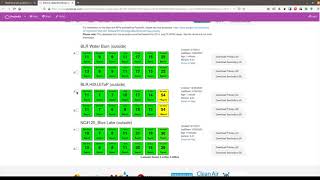
The PurpleAir sensor should post data to the PurpleAir website so long as the sensor has network access. In order to download historic data or generate usable data artifacts, navigate to the PurpleAir website (purpleair.com), select the sensor, hover over "get this Widget", and select "Download".

Next, input a start and end date, choose an average data resolution (we suggest "none" for 2-minute resolution data), select channels A and B, then click "download"

The data is now downloaded as two separate CSV files. These can be visualized and analyzed with your program of choice (in this case, R)
Video Guide to downloading PurpleAir data[edit | edit source]
In addition to the instructions above, this video guide to downloading PurpleAir data may be useful.