| (One intermediate revision by the same user not shown) | |||
| Line 44: | Line 44: | ||
#Proceed to electrical setup section | #Proceed to electrical setup section | ||
===Electrical Assembly Instructions=== | ===Electrical Assembly Instructions / Software=== | ||
#Wire stepper motor according to [http://fritzing.org/media/fritzing-repo/projects/a/a4988-single-stepper-test/images/Arduino%20A4988%20Single%20Stepper%20Wiring_bb.jpg this] diagram<ref> | #Wire stepper motor according to [http://fritzing.org/media/fritzing-repo/projects/a/a4988-single-stepper-test/images/Arduino%20A4988%20Single%20Stepper%20Wiring_bb.jpg this] diagram<ref> | ||
http://fritzing.org/projects/a4988-single-stepper-test/ | http://fritzing.org/projects/a4988-single-stepper-test/ | ||
| Line 159: | Line 159: | ||
===Possible Solutions=== | ===Possible Solutions=== | ||
#For all problems above move motor underneath and direct mount to diffraction mount | #For all problems above move motor underneath and direct mount to diffraction mount | ||
== References == | == References == | ||
Revision as of 23:02, 10 November 2015
Understanding the market
Monochromators are used in optics to isolate certain wavelengths from a light source made up of many wavelengths. [1] Monochromators on the market are anywhere from $2000 to $10,000. Our monochromator is made for less than $100.
Project goals
The goal for this project was to create an easily 3D printed and assembled monochromator that is still relatively accurate.
Design
- Monochromator Parts
-
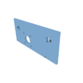
Monochromator Wall
-
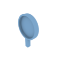
Monochromator Base Plate
-
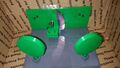
View of diffraction grating
-
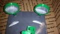
View of concave mirrors
-
View of enclosure front
-
Top view of monochromator


Mechanical Assembly Instructions
- Purchase mirrors, bolts, nuts, razor blades, stepper motor, and associated electronics
- Print files from NIH site http://3dprint.nih.gov/discover/3dpx-002158
- Epoxy mirrors into printed mirror holders and leave until dry
- Cut 1" by 1" square from edge of DVD-R and epoxy to mirror holder face
- Epoxy 16mm M3 bolt onto end of stepper motor
- Push M3 nuts into pockets on back of front wall
- Bolt razor blades onto wall with sharp edge pointed into center of wall
- Bolt stepper motor to wall using 4 bolts, with 2 washers under each bolt
- Bolt wall to base with 2 M3 bolts
- Push first mirror holder into square slot on base pointed toward front wall and insert bolt from underneath to secure, repeat with second mirror holder
- Push M3 nut into pin for diffraction grating mount
- Place pin into arms on diffraction grating mount
- Place diffraction grating mount into hole on base plate
- Rotate pin so that the nut side is closest to the stepper motor and rotate the motor by hand to start the bolt into the nut
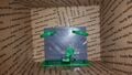
- Place assembly into cardboard box, mark out holes for motor and slots
- Remove assembly, cut out holes, place assembly back in box
- Tape assembly to bottom and front of box being careful to not cover inlet and outlet slots with tape
- Proceed to electrical setup section
Electrical Assembly Instructions / Software
#include <Stepper.h>

const int stepsPerRevolution = 200;  // change this to fit the number of steps per revolution
// for your motor

// initialize the stepper library on pins 8 through 11:
//Stepper myStepper(stepsPerRevolution, 4, 5);

int stepCount = 0;         // number of steps the motor has taken

void setup() {
  pinMode(6,OUTPUT); // Enable
  pinMode(5,OUTPUT); // Step
  pinMode(4,OUTPUT); // Dir

  // initialize the serial port:
  Serial.begin(9600);
}

void loop() {
  // step one step:
  Serial.println("Please Enter Step Value (-50 to 50): ");
  while (Serial.available() == 0);
  int val = Serial.parseInt(); //read int or parseFloat for ..float...
  if(abs(val) > 50) {
    Serial.println("ERROR: Too High of Input Value.");
    goto failed;
  }
  if(val < 0) {
      digitalWrite(4,HIGH); // Set Dir high
  }
  else {
    digitalWrite(4,LOW); // Set Dir low
  }
  for(int i = 0; i < abs(val); i++) {
    digitalWrite(5,HIGH); // Output high
    delayMicroseconds(500); // Wait 1/2 a ms
    digitalWrite(5,LOW); // Output low
    delayMicroseconds(500); // Wait 1/2 a ms
  }
  Serial.print("Moved ");
  Serial.print(val);
  Serial.println(" Steps.");
  stepCount++;
  failed:;
  //delay(500);
}
Calibration
- Due to the many types of mirrors and DVDs available calibration is recommended
- Acquire a white light source and spectrometer
- Move the mirror to the maximum and minimum travel and record the prevalent wavelength
- Take additional points if necessary at known number of stepper motor rotations
- Use either a best fit linear line or polynomial to calculate wavelength output vs stepper motor rotations
Costs
| Item | Quantity | Approximate Cost |
|---|---|---|
| Plastic | 163 g at 25% fill | $3.75 |
| 50 mm dia, 100 mm focal length Concave Mirrors | 2 | $10 |
| Razor Blades | 2 | $1 |
| NEMA 17 Stepper Motor | 1 | $20 |
| M3x0.5 10 mm bolts | 8 | $4 |
| M3x0.5 nuts | 3 | $2 |
| Arduino | 1 | $20 |
| Stepper Motor Driver | 1 | $20 |
| Breadboard | 1 | $8 |
Discussion
Current Issues
- Diffraction mount will not actually rotate in current configuration
- Setup in now too heavy on motor side
- Motor is also in the way of light openings
Possible Solutions
- For all problems above move motor underneath and direct mount to diffraction mount
References
- ↑ Monochromator Wikipedia [1]
- ↑ http://fritzing.org/projects/a4988-single-stepper-test/