|[[File:MOST_syringe_pump_material.JPG|thumb|400px|alt=Materials for syringe pump|Parts for syringe pump assembly.]]
|[[File:MOST_syringe_pump_material.JPG|thumb|400px|alt=Materials for syringe pump|Parts for syringe pump assembly.]]
{|class="wikitable" style="margin:auto"
{|class="wikitable" style="margin:auto"
|+Materials
|+Materials
!Description
!Description
!Count
!Count
|-
|-
|blah
|Motor End
|1
|1
|-
|-
|blah
|Carriage
|1
|1
|-
|-
|blah
|Plunger Holder base and tab
|1
|1
|-
|-
|blah
|Body Holder
|2
|-
|Idler End
|1
|1
|-
|-
|blah
|NEMA17 motor
|1
|1
|-
|-
|blah
|6mm x 6mm shaft coupling
|1
|-
|625z ball bearing
|2
|-
|LN6UU linear bearing
|2
|-
|M3 x 10mm socket head cap screw
|6
|-
|M3 x 16mm socket head cap screw
|4
|4
|-
|-
|blah
|12
|M3 x 16mm socket head cap screw
|4
|-
|-
|blah
|4
|M3 x 20mm socket head cap screws
|3
|-
|-
|blah
|24
|M3 hex nut
|13
|-
|-
|blah
|18
|M5 hex nut
|5
|-
|-
|blah
|3
|M5 threaded rod
|0.2 m
|-
|-
|blah
|1
|6mm A2 tool steel
|0.4 m
|}
|}
|
|
|[[File:MOST_syringe_pump_tools.JPG|thumb|400px|alt=Necessary tools|Necessary tools for assembling syringe pump.]]
|[[File:MOST_syringe_pump_tools.JPG|thumb|400px|alt=Necessary tools|Necessary tools for assembling syringe pump.]]
{|class="wikitable" style="margin:auto"
{|class="wikitable" style="margin:auto"
|+Tools
|+Tools
|-
|-
|blah
|-
|M3 allen key
|blah
|-
|-
|3mm drill bit
|3mm drill bit
|-
|-
|blah
|exacto knife
|-
|-
|Screwdriver
|Screwdriver
|}
|}
|}
|}
{{clear}}
{{clear}}
=Procedure=
=Procedure=
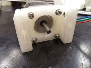
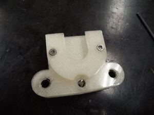
# [[File:MOST_step01.JPG|thumb|right|Motor end mounted to motor.]]Secure motor into the motor end using 4 M3 washers and 4 M3 x 20mm socket head cap screws.{{clear}}
#[[File:MOST_step01.JPG|thumb|right|Motor end mounted to motor.]]Secure motor into the motor end using 4 M3 washers and 4 M3 x 20mm socket head cap screws.{{clear}}
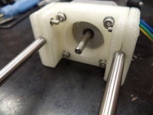
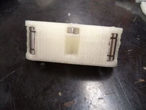
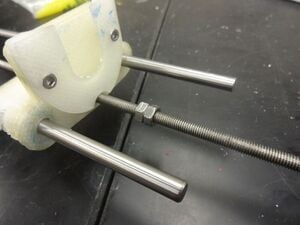
#[[File:MOST_step02.JPG|thumb|right|Metal rods inserted in motor end.]]Insert the 2 metal rods into motor end, then secure them in place with 2 M3 nuts and 2 M3 x 10mm socket head cap screws.{{clear}}
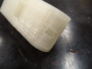
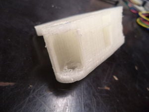
#[[File:MOST_step031.JPG|thumb|right|Not hollowed-out carriage.]][[File:MOST_step032.JPG|thumb|right|Hollowed out carriage.]]Hollow out the two ends of the carriage, with a handheld drill bit or knife to make a hole in the plastic.{{clear}}
#[[File:MOST_step04.JPG|thumb|right|Linear bearings and nut inserted in the carriage.]] Snap the linear bearings into place on the hollowed out ends of the carriage. Then insert an M5 nut into the nut-trap on the bottom of the carriage.{{clear}}
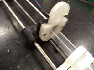
#[[File:MOST_step05.JPG|thumb|right|Base of the plunger holder attached to carriage]]Attach the base of the Plunger holder to the carriage with 2 M3 nuts and 2 M3 x 10mm socket head cap screws.{{clear}}
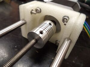
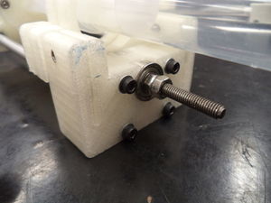
#[[File:MOST_step06.JPG|thumb|right|Threaded rod coupled to motor.]] Insert threaded rod into the coupler halfway, the other half should be on the motor, secure it. {{clear}}
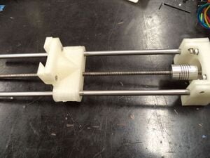
#[[File:MOST_step07.JPG|thumb|right|Carriage threaded onto the rods.]] Slide the carriage onto the threaded rod and make sure the two metal rods fit into the linear bearings.{{clear}}
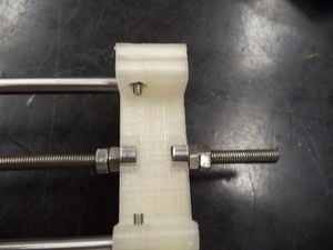
#[[File:MOST_step08.JPG|thumb|right|M5 nutes mounted on threaded rod.]] After the carriage is midway down the threaded rod, thread two M5 nuts onto the threaded rod. {{clear}}
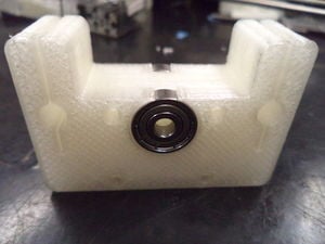
#[[File:MOST_step09.JPG|thumb|right|Bearings inserted into the idler end.]] Insert the two bearings into the circular slots in the idler end. {{clear}}
#[[File:MOST_step10.JPG|thumb|right|Idler end mounted on the rods.]] Now slide the idler end onto the rods and secure it with two more M5 nuts on the end of the threaded rod. Push the two nuts already on the rod up to the idler end to secure it. {{clear}}
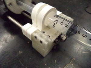
#[[File:MOST_step11.JPG|thumb|right|Syringe in the body and plunger holders.]] Insert the syringe body into the body holders, then slide the plunger into the base of the plunger holder. {{clear}}
#[[File:MOST_step12.JPG|thumb|right|Syringe in the body and plunger holders.]] Using four M3 x 40mm bolts, four M3 washers, and four M3 nuts secure the two holding pieces to the idler end of the pump. Put two nuts it the top of the holder closer to the carriage and two nuts in the bottom of the holder against the idler end. {{clear}}
#[[File:MOST_step13.JPG|thumb|right|Mounted syringe.]] Insert the tab of the plunger holder on top of the plunger to secure it to the pump and prevent slipping when in use. {{clear}}
Full instructions, documentation, data, and pictures coming soon....
Materials and Tools
Parts for syringe pump assembly.
Materials
Description
Count
Motor End
1
Carriage
1
Plunger Holder base and tab
1
Body Holder
2
Idler End
1
NEMA17 motor
1
6mm x 6mm shaft coupling
1
625z ball bearing
2
LN6UU linear bearing
2
M3 x 10mm socket head cap screw
6
M3 x 16mm socket head cap screw
4
M3 x 16mm socket head cap screw
4
M3 x 20mm socket head cap screws
3
M3 hex nut
13
M5 hex nut
5
M5 threaded rod
0.2 m
6mm A2 tool steel
0.4 m
Necessary tools for assembling syringe pump.
Tools
M3 allen key
3mm drill bit
exacto knife
Screwdriver
Procedure
Motor end mounted to motor.Secure motor into the motor end using 4 M3 washers and 4 M3 x 20mm socket head cap screws.
Metal rods inserted in motor end.Insert the 2 metal rods into motor end, then secure them in place with 2 M3 nuts and 2 M3 x 10mm socket head cap screws.
Not hollowed-out carriage.Hollowed out carriage.Hollow out the two ends of the carriage, with a handheld drill bit or knife to make a hole in the plastic.
Linear bearings and nut inserted in the carriage. Snap the linear bearings into place on the hollowed out ends of the carriage. Then insert an M5 nut into the nut-trap on the bottom of the carriage.
Base of the plunger holder attached to carriageAttach the base of the Plunger holder to the carriage with 2 M3 nuts and 2 M3 x 10mm socket head cap screws.
Threaded rod coupled to motor. Insert threaded rod into the coupler halfway, the other half should be on the motor, secure it.
Carriage threaded onto the rods. Slide the carriage onto the threaded rod and make sure the two metal rods fit into the linear bearings.
M5 nutes mounted on threaded rod. After the carriage is midway down the threaded rod, thread two M5 nuts onto the threaded rod.
Bearings inserted into the idler end. Insert the two bearings into the circular slots in the idler end.
Idler end mounted on the rods. Now slide the idler end onto the rods and secure it with two more M5 nuts on the end of the threaded rod. Push the two nuts already on the rod up to the idler end to secure it.
Syringe in the body and plunger holders. Insert the syringe body into the body holders, then slide the plunger into the base of the plunger holder.
Syringe in the body and plunger holders. Using four M3 x 40mm bolts, four M3 washers, and four M3 nuts secure the two holding pieces to the idler end of the pump. Put two nuts it the top of the holder closer to the carriage and two nuts in the bottom of the holder against the idler end.
Mounted syringe. Insert the tab of the plunger holder on top of the plunger to secure it to the pump and prevent slipping when in use.