The printable version is no longer supported and may have rendering errors. Please update your browser bookmarks and please use the default browser print function instead.
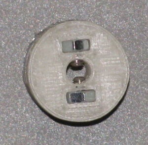
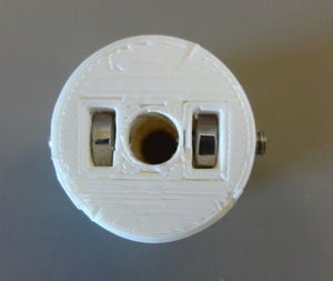
With a 5mm drill bit, ream the shaft hole in the pulley. If necessary, open the set screw nut traps in the pulley with a sharp knife.
.Put two M3 nuts in the pulley, and put the set screws in them. Screw them in so you can clearly see them in the shaft.
.Screw the set screws back out, so that the shaft is entirely clear.
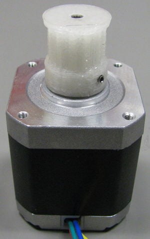
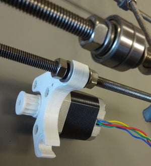
.Then put the pulley on the motor with the set screws towards the motor body.
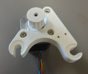
Screw 2 mm screws into the small holes of the motor mount, so that there is a thread in the plastic. If it's hard to start the screw, you can chamfer the top of the hole with the tip of a 3 mm drill.
Remove the 2 mm screws out and set aside.
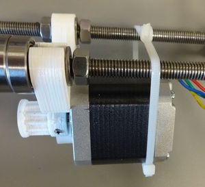
.Attach the motor mount to the motor as shown. Note the orientation of the motor.
.Attach the motor to the bottom front threaded rod. Don't tighten the nuts yet.
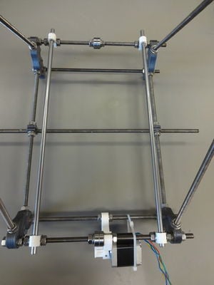
.Attach it to the top rod. Don't tighten the nuts. Don't use the zip-ties yet.
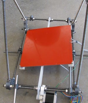
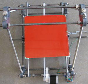
.The frame should now look like this.
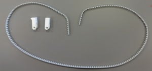
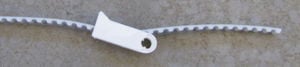
.Next we assemble the belt.
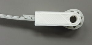
.Insert the belt into a terminator so it sticks out approximately 15 teeth. Let it come out so the teeth of the belt will be on the inside.
.Insert the end of the belt back into the terminator, so the teeth lock together. Pull the belt out on the free side so it locks itself.
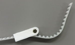
.Attach the flagged belt terminator to the other side of the belt. Make sure that the long end of the belt is coming out on the side of the flag (the flag should be pointed down with printer on its feet). Back feed the belt as previously.
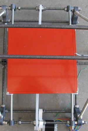
.BE SURE THAT THE EPOXY HAS HAD ENOUGH TIME TO CURE PRIOR TO DOING THIS STEP. Attach the carriage to the frame. Start with the right smooth rod and tighten the clamp. First push the rod through the carriage, then insert it in the clamps.
.Push the other rod through the carriage on the left side.
.Then push the rod through its clamps, but don't tighten them.
Move the carriage back and forth to find the optimal position for the clamps. Then tighten the nuts on them.
Attach the belt, making sure that it runs around the 2 sets of bearings and the pulley on the motor. The terminator with the flagged end will be closest to the motor. Use a large zip tie to hook the ends of the belt together. When cutting the zip tie off, leave enough so that you can grab it and tighten it some time in the future, as needed.
Make sure the carriage can move so the bearing saddles can touch the frame clamps. You may need to file the top off the clamps to make this possible.
Starting at the motor end, move the motor and idler so that the belt is aligned with the belt dog under the carriage. Move the y-carriage back and forth several times to ensure that the belt remains relatively centered on the idler bearings. Tighten the nuts for the motor and the idler.
Move the flagged belt terminator on the y-drive belt as close to the y-axis motor as it can be and then move the y-carriage all the way to the opposite end and engage the belt dog with the belt.
Attach the y-axis limit switch to the y-motor mount using a pair of M2 x 10mm screws with washers. If the belt terminator runs into the bottom of the motor mount, move the bottom of the motor mount out of the way by loosening the nuts on either side of it, repositioning it out of the way and tightening the nuts.