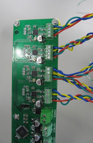
Working with one axis at a time, attach the motor leads to the printer controller as shown (blue, yellow, green, red from top to bottom, as shown in picture). The z-axis motors are both attached to the z-axis terminals (motors in parallel). Attach the limit switch for the current axis to the appropriate end stop terminals. There is no polarity for the end stop switches, so no need to put the wires in the terminals a certain way.
Attach the extruder motor leads to the printer controller in exactly the same way as the axes motors.
Attach the leads for the hot end power resistor (thicker conductors) to the hot end power terminals and attach the hot end thermistor to the hot end temperature terminals. Polarity is not a concern with these devices.
Attach the heated bed power leads (thicker conductors) to the heated bed power terminals and the heated bed thermistor to the heated bed temperature terminals. There is no polarity with these devices.
Route all the wires to the Melzi; leave enough slack for moving parts to freely move. Neatness pays off as good routing of wires facilitates future maintenance of the printer.
Clamp the negative probe of a volt meter to the negative (ground) terminal in the main power terminal. Make sure the system is unplugged from the AC outlet.
Attach the USB cable between the controller and a computer and ensure that the shorting block on the pins in the middle of the printer controller are set so the left-most pair of pins are shorted (controller powered over USB).
Set the voltmeter to DC millivolts and locate the the point on the small potentiometers under the motor controller chips on the printer controller (see picture) to contact with the positive probe of the voltmeter. One axis at a time, adjust the potentiometers for the x-axis, y-axis and extruder such that the voltmeter reads on or about 420 millivolts (0.42 V). (The motors specified are 1.5 A steppers; the Melzi board requires a reference voltage of 0.28 * Imotor to control current; 0.28 * 1.5 = 0.42 V.)
Set the reference voltage for the z-axis motors to 840 millivolts (0.84 V).