No edit summary |
No edit summary |
||
| Line 5: | Line 5: | ||
=== Reasons for the Rebuild: === | === Reasons for the Rebuild: === | ||
<ol> | <ol> | ||
[[Image:SquigglyCut.jpg|thumb|left]] | |||
<li> | |||
A substantial portion of the cutting bed could be re-claimed by redesigning the components increasing the working area of the laser cutter | |||
</li> | </li> | ||
<li> | <li> | ||
The prior designed linear motion system presented mechanics that were easy to mis-align. The movement of the gantry would cause the bearings to slightly loosen. This caused jittering in the cuts as seen below. More severe examples exist but the stock could not be located for this documentation | |||
</li> | |||
<li> | |||
The far ends of the gantry were statically linked by one axle with one motor. This made it extremely difficult to get a true alignment with the gantry. | The far ends of the gantry were statically linked by one axle with one motor. This made it extremely difficult to get a true alignment with the gantry. | ||
</li> | |||
<li> | |||
For proof of concept. Similair designs for inexpensive linear motion have been implemented in a wide range of applications. Mainly for cnc mill's. This rebuild was partially under the intention of testing and displaying functionality of that implementation and appropriateness on a laser cutter. | |||
</li> | |||
<li> | |||
One of the benefits of this design is the simplicity to remove the gantry entirely in case you need to make modifications or preform maintenance. | |||
</li> | |||
</ol> | </ol> | ||
<h3>A Note on this implementation:</h3> | |||
<p>The dynamic motion of the components used in this application were more complex and less functional then other designs. While this design works there are simpler methods of achieving the same and better results. There are elements of this design that could be greatly optimized.</p> | <h3> | ||
A Note on this implementation: | |||
</h3> | |||
<p> | |||
The dynamic motion of the components used in this application were more complex and less functional then other designs. While this design works there are simpler methods of achieving the same and better results. There are elements of this design that could be greatly optimized. | |||
</p> | |||
<br> | <br> | ||
<h2>The Rebuild:</h2> | |||
<h3 style="margin-left: 20px">Required Tools:</h3> | <h2> | ||
The Rebuild: | |||
</h2> | |||
<h3 style="margin-left: 20px"> | |||
Required Tools: | |||
</h3> | |||
<ul> | <ul> | ||
<li>3d Printer capable of printing pla and ninja flex with a minimum print dimension of 8x8x6 inches</li> | <li>3d Printer capable of printing pla and ninja flex with a minimum print dimension of 8x8x6 inches</li> | ||
<li>Center Punch</li> | |||
<li>Hammer</li> | |||
<li>Drill</li> | |||
<li>Drill Bit Set</li> | |||
<li>Allen Wrench Set</li> | <li>Allen Wrench Set</li> | ||
<li>Needle nose Pliers</li> | <li>Needle nose Pliers</li> | ||
<li>Soldering Iron | <li>Soldering Iron</li> | ||
<li>Lighter for heat shrink tubing</li> | |||
<li>Wire Strippers</li> | <li>Wire Strippers</li> | ||
</ul> | </ul> | ||
<h3 style="margin-left: 20px">Bill Of Materials:</h3> | |||
<h4>Electronics and Wiring</h4> | <h3 style="margin-left: 20px"> | ||
Bill Of Materials: | |||
</h3> | |||
<h4> | |||
Electronics and Wiring | |||
</h4> | |||
<ul> | <ul> | ||
<li>Male+Female 4 Pin Connector with wire for 5050/3528 RGB Led Driver/Strip. [https://www.picclickimg.com/00/s/ODAwWDgwMA==/z/GYAAAOSwJkJWjzyX/$/20X-MaleFemale-4-Pin-Connector-with-wire-for-_57.jpg] I use these connectors for all of my stepper motors in every project.</li> | <li>Male+Female 4 Pin Connector with wire for 5050/3528 RGB Led Driver/Strip. [https://www.picclickimg.com/00/s/ODAwWDgwMA==/z/GYAAAOSwJkJWjzyX/$/20X-MaleFemale-4-Pin-Connector-with-wire-for-_57.jpg] I use these connectors for all of my stepper motors in every project.</li> | ||
| Line 51: | Line 88: | ||
<li>12 x m2x10mm. 2 for each limit switch.</li> | <li>12 x m2x10mm. 2 for each limit switch.</li> | ||
</ul> | </ul> | ||
<h4>Software. This assumes use of the smoothieboard as a control board</h4> | |||
<h4> | |||
Software. This assumes use of the smoothieboard as a control board | |||
</h4> | |||
<ul> | <ul> | ||
<li>Use the open source software "Pronterface" for controlling the laser cutter</li> | <li> | ||
<li>Customized smoothieboard firmware found [https://github.com/T8er].</li> | Use the open source software "Pronterface" for controlling the laser cutter | ||
</li> | |||
<li> | |||
Customized smoothieboard firmware found [https://github.com/T8er]. | |||
</li> | |||
</ul? | |||
<h3> | |||
NOTE: It is a good idea to remove and store your laser tube from the chassis of the laser cutter for the entirety of the reconstruction. This will help ensure you do not accidentally damage the laser tube which is generally more expensive then the cumulative price of the other components of the laser cutter. | |||
</h3> | |||
<h3> | |||
Step 1: Remove old mechanical components from the lasersaur. | |||
</h3> | |||
<ol> | <ol> | ||
<li>Remove the belts driving the gantry and focusing lens carriage.</li> | <li>Remove the belts driving the gantry and focusing lens carriage.</li> | ||
| Line 69: | Line 120: | ||
</ol> | </ol> | ||
[[Image:Lasersaur remove elements photo.jpg]] | [[Image:Lasersaur remove elements photo.jpg]] | ||
<h3> | <h3> | ||
At this point the inside of the laser cutter chassis should contain no components other than those of the frame. No limit switches or limit switch mounting hardware, no electrical components of any kind and no | At this point the inside of the laser cutter chassis should contain no components other than those of the frame. No limit switches or limit switch mounting hardware, no electrical components of any kind and no | ||
| Line 74: | Line 126: | ||
</h3> | </h3> | ||
<h2>Solder the electronic components </h2> | <h2> | ||
Step 2: Mount the guide rails: | |||
</h2> | |||
<ol> | |||
<li> | |||
Cut your aluminum stock to the y length of the chassis. This will be around 33 and 3/4 inch length. | |||
</li> | |||
<li> | |||
Using a center punch and a ruler, punch drill guide points in the aluminum stock in 9 places evenly spaced across the stock. This should give you intervals between punches roughly 4 and 1/4 inch apart. | |||
</li> | |||
<li> | |||
Use a drill with a bit as close to and slightly larger then 5mm as possible to drill out the punched locations in the stock. | |||
</li> | |||
<li> | |||
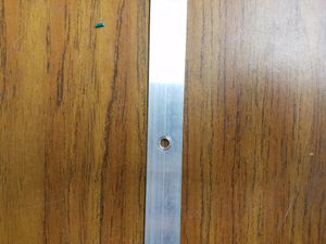
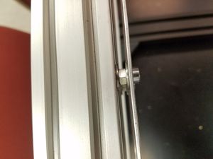
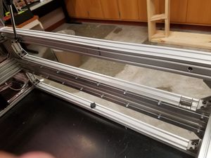
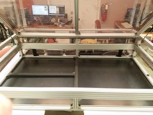
Using the low profile 12mm m5 screws, 2 m5 washers per screw and an m5 nut (non-locking) Mount the stock to the top and bottom t-slots of both the left and right sided 80x40mm t-slot chassis frame extrusions. | |||
Place a t-slot m5 slot nut in the rail, then a washer then a nut then a washer then the aluminum stock and thread the nut through that order of components as seen in the pictures. | |||
[[Image:Drillandpunch.jpg|thumb]] | |||
[[Image:StockHardwareConfiguration.jpg|thumb]] | |||
[[Image:StockMounted.jpg|thumb]] | |||
[[Image:FullMount.jpg|thumb]] | |||
</li> | |||
</ol> | |||
<h2> | |||
Solder the electronic components | |||
</h2> | |||
<ol> | <ol> | ||
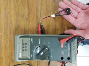
<li>Begin by soldering your limit switches. This will give you soldering practice for when you get to your stepper motors. Use a normally closed configuration for your limit switches. This ensures that in the case of a faulty switch a limit break will register with the control system not allowing motion. Solder a male connector to the switch. Use male connectors whenever a static component's terminals can be touched with no effect. for example with a power supply you would have the plug coming out of the psu be female because you cannot accidentally connect the power terminals. On the other end such as the control board connected to that power supply you would have male connectors since accidentally connecting the terminals of the connector is not possible if it is connected to the power supply indicating no power would be in the board and no damage possible. Use 3/32 inch heat shrink tubing to cover the solder joints. Test all your limit switches wit a multimeter by turing the function to the logical not symbol, this beeps when the two probes of the multimeter are touching each other. Connect the multi meter probes to the limit switch wires. The multimeter should make a beep when the switch is not activated or not pressed. The multimeter should stop beeping when you press the limit switch or open the circuit. Orientation of the connectors does not matter. | <li> | ||
Begin by soldering your limit switches. This will give you soldering practice for when you get to your stepper motors. Use a normally closed configuration for your limit switches. This ensures that in the case of a faulty switch a limit break will register with the control system not allowing motion. Solder a male connector to the switch. Use male connectors whenever a static component's terminals can be touched with no effect. for example with a power supply you would have the plug coming out of the psu be female because you cannot accidentally connect the power terminals. On the other end such as the control board connected to that power supply you would have male connectors since accidentally connecting the terminals of the connector is not possible if it is connected to the power supply indicating no power would be in the board and no damage possible. Use 3/32 inch heat shrink tubing to cover the solder joints. Test all your limit switches wit a multimeter by turing the function to the logical not symbol, this beeps when the two probes of the multimeter are touching each other. Connect the multi meter probes to the limit switch wires. The multimeter should make a beep when the switch is not activated or not pressed. The multimeter should stop beeping when you press the limit switch or open the circuit. Orientation of the connectors does not matter. [[Image:NOLimitSwitch.jpg|thumb]] | |||
</li> | </li> | ||
<li>Repeat step 1 until you have 6 functionally wired limit switches.</li> | |||
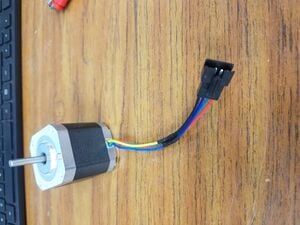
<li>Solder the 4 pin connectors to you stepper motors. Your stepper motors should have the same wiring color scheme as the connectors. If that is not the case, refer to the documentation for your stepper motors and stepper motor wiring color schemes for the proper configurations. Again because touching all the terminals of a disconnected stepper motor will not damage the motor in any way use a male connector</li> | <li> | ||
Repeat step 1 until you have 6 functionally wired limit switches. | |||
</li> | |||
<li> | |||
Solder the 4 pin connectors to you stepper motors. Your stepper motors should have the same wiring color scheme as the connectors. If that is not the case, refer to the documentation for your stepper motors and stepper motor wiring color schemes for the proper configurations. Again because touching all the terminals of a disconnected stepper motor will not damage the motor in any way use a male connector | |||
[[Image:ConnectedStepper.jpg|thumb]] | |||
</li> | |||
</ol> | </ol> | ||
<h1>To Be Continued...</h1> | |||
Revision as of 21:42, 28 April 2017
LaserSaur laser cutter motion components redesign and custom firmware
Open Source Hardware Enterprise of Michigan Technological University purchased an open source laser cutter called the "lasersaur". While the design was adequate with testing we decided to attempt improvements on the motion components of the laser cutter.
Reasons for the Rebuild:
- A substantial portion of the cutting bed could be re-claimed by redesigning the components increasing the working area of the laser cutter
- The prior designed linear motion system presented mechanics that were easy to mis-align. The movement of the gantry would cause the bearings to slightly loosen. This caused jittering in the cuts as seen below. More severe examples exist but the stock could not be located for this documentation
- The far ends of the gantry were statically linked by one axle with one motor. This made it extremely difficult to get a true alignment with the gantry.
- For proof of concept. Similair designs for inexpensive linear motion have been implemented in a wide range of applications. Mainly for cnc mill's. This rebuild was partially under the intention of testing and displaying functionality of that implementation and appropriateness on a laser cutter.
- One of the benefits of this design is the simplicity to remove the gantry entirely in case you need to make modifications or preform maintenance.

A Note on this implementation:
The dynamic motion of the components used in this application were more complex and less functional then other designs. While this design works there are simpler methods of achieving the same and better results. There are elements of this design that could be greatly optimized.
The Rebuild:
Required Tools:
- 3d Printer capable of printing pla and ninja flex with a minimum print dimension of 8x8x6 inches
- Center Punch
- Hammer
- Drill
- Drill Bit Set
- Allen Wrench Set
- Needle nose Pliers
- Soldering Iron
- Lighter for heat shrink tubing
- Wire Strippers
Bill Of Materials:
Electronics and Wiring
- Male+Female 4 Pin Connector with wire for 5050/3528 RGB Led Driver/Strip. [1] I use these connectors for all of my stepper motors in every project.
- IEC320 C14 Inlet Socket. This is a standard computer mains 3 prong plug. The IE number and c14 are standards for classifying this power socket
- JST XH 2.5-2 Pin Battery Connector Plug Female & Male with 120MM Wire. These are used for the limit switches, any 2 prong male female connectors will suffice
- 6 x TEMCo Micro Limit Switch Lever Arm Subminiature SPDT Snap Action. These are the limit switches for x,y min and max
- Smoothieboard V1 found [2]. I do not recommend using this control board. This board is inconsistent with flashing firmware and setting up the configuration but it is what I currently have installed.
- 2 x 17hs16-2004s1 Nema 17 Stepper Motors for the Y axis motion. these can be swapped for different nema 17's as long as you have two identical steppers with current rating of less than or equal to 2.0 amps
- Linear Engineering 4118s-01 Nema 17 for the x axis. This came with the original Lasersaur bill of materials and may be discontinued. If so, a standard nema 17 1.5a 1.8 degree step angle will sufice.
- 5 volt ac-dc power supply (rs-75-5)
- 24 volt ac-dc power supply (rs-75-24)
Hardware
- High Carbon Steel V Groove Guide Pulley Rail Ball Bearings Wheel 3*12*4mm. These allow the gantry plates to ride on the rails
- Inventables 1800 mm makerslide found [3]. This is for the x axis focusing mirror carriege
- 4x Inventables Dual Bearing V-Wheel Kit
- M5-0.80x12 MM,(FT) Socket Cap Screws Cap Screw. These hold the guide rails to the frame of the laser cutter. It is very important that the head of these screws be low profile to allow the gantry plates to pass over them with proper clearance
- Flanged Shielded Bearing MF84ZZ 4x8x3 Miniature. For the rotation components on the gantry plates.
- 12 x m2x10mm. 2 for each limit switch.
Software. This assumes use of the smoothieboard as a control board
- Use the open source software "Pronterface" for controlling the laser cutter
- Customized smoothieboard firmware found [4]. </ul?
- Remove the belts driving the gantry and focusing lens carriage.
- Remove the refraction mirrors.
- Remove the limit switch mounts and the belt caster mounts.
- Remove the stepper motors.
- Remove the gantry and remaining drive components.
- Remove the build platform and platform spacing mesh from the floor of the chassis.
- Finally, remove the two t-slot extruded aluminum bars that travel from the front to the back of the lasercutter inner chassis. These are located on the far left and far right sides
- Cut your aluminum stock to the y length of the chassis. This will be around 33 and 3/4 inch length.
- Using a center punch and a ruler, punch drill guide points in the aluminum stock in 9 places evenly spaced across the stock. This should give you intervals between punches roughly 4 and 1/4 inch apart.
- Use a drill with a bit as close to and slightly larger then 5mm as possible to drill out the punched locations in the stock.
-
Using the low profile 12mm m5 screws, 2 m5 washers per screw and an m5 nut (non-locking) Mount the stock to the top and bottom t-slots of both the left and right sided 80x40mm t-slot chassis frame extrusions.
Place a t-slot m5 slot nut in the rail, then a washer then a nut then a washer then the aluminum stock and thread the nut through that order of components as seen in the pictures.
-
Begin by soldering your limit switches. This will give you soldering practice for when you get to your stepper motors. Use a normally closed configuration for your limit switches. This ensures that in the case of a faulty switch a limit break will register with the control system not allowing motion. Solder a male connector to the switch. Use male connectors whenever a static component's terminals can be touched with no effect. for example with a power supply you would have the plug coming out of the psu be female because you cannot accidentally connect the power terminals. On the other end such as the control board connected to that power supply you would have male connectors since accidentally connecting the terminals of the connector is not possible if it is connected to the power supply indicating no power would be in the board and no damage possible. Use 3/32 inch heat shrink tubing to cover the solder joints. Test all your limit switches wit a multimeter by turing the function to the logical not symbol, this beeps when the two probes of the multimeter are touching each other. Connect the multi meter probes to the limit switch wires. The multimeter should make a beep when the switch is not activated or not pressed. The multimeter should stop beeping when you press the limit switch or open the circuit. Orientation of the connectors does not matter.
- Repeat step 1 until you have 6 functionally wired limit switches.
-
Solder the 4 pin connectors to you stepper motors. Your stepper motors should have the same wiring color scheme as the connectors. If that is not the case, refer to the documentation for your stepper motors and stepper motor wiring color schemes for the proper configurations. Again because touching all the terminals of a disconnected stepper motor will not damage the motor in any way use a male connector
NOTE: It is a good idea to remove and store your laser tube from the chassis of the laser cutter for the entirety of the reconstruction. This will help ensure you do not accidentally damage the laser tube which is generally more expensive then the cumulative price of the other components of the laser cutter.
Step 1: Remove old mechanical components from the lasersaur.

At this point the inside of the laser cutter chassis should contain no components other than those of the frame. No limit switches or limit switch mounting hardware, no electrical components of any kind and no motion hardware components of any kind. A perfect rectangle should be formed by the t-slot aluminum extrusion of the chassis frame with no interfering or protruding parts.
Step 2: Mount the guide rails:


Solder the electronic components

