The printable version is no longer supported and may have rendering errors. Please update your browser bookmarks and please use the default browser print function instead.
The MOST Delta uses a j-head hot end with a 0.5mm nozzle and accepting 1.75mm filament. There are a few versions of the j-head - the one discussed here has the PEEK insulator and is designed for PLA and ABS filament. Even this design has a couple variants, one using a tiny radial lead thermistor and another using an axial lead thermistor. The axial lead thermistor version is recommended as the thermistor leads are much more robust as compared to the brittle, hair-thin leads of the radial lead version. Regardless of the design variant, assembly is essentially identical.
Procedure
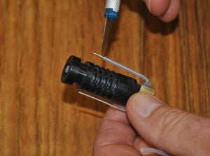
Smear muffler cement on heating resistor.Insert resistor and bend leads.Smear a small amount of muffler cement around the entire exterior of the heating resistor and insert into the hole provided for it in the hot end. Carefully bend the resistor leads up towards the top of the hot end heat sink.
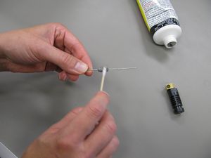
Insert thermistor with muffler cement on it.Apply a small amount of muffler cement to the glass bulb of the thermistor and press into the hole in the hot end. Use a toothpick or similar item to clean away any excess cement on the exterior of the hot end. Set the hot end aside to let the cement cure.
Trimmed PTFE insulation.Check to see that the muffler cement has set around the hot end thermistor and power resistor. If it has, carefully slide on the PTFE tubing provided for the thermistor and resistor leads. Trim the PTFE tubing so that the entire lead is insulated except for about 1/4" at the end of the lead. Each lead should be insulated by PTFE.
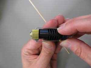
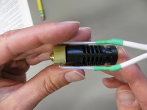
File:MOST Delta 005 NEW.JPGKapton tape securing leads to hot end.To minimize the possibility of breaking the thermistor leads while soldering, carefully and tightly wrap kapton tape around the bottom of the heat sink near the nozzle, making at least three complete turns around the heat sink. Do not wrap tape such that the openings in the heat sink are blocked or cooling of the hot end entry point will be impaired.
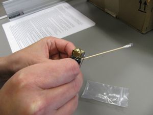
Heating resistor conductor soldered on.Butt join the tinned 18ga speaker wire or lamp cord to the heating resistor leads.
Butt join a 1m length of copper pair to the thermistor leads.


