The Hydraulic Ram Pump, Hydram, or simply Ram Pump is an automatic pumping device that is capable of pumping water higher than its original source without using electricity or any other power source. It uses just two moving parts, and it is therefore mechanically very simple. This gives it very high reliability, minimal maintenance requirements and a long operation life.


The Hydraulic Ram Pump, Hydram, or simply a Ram Pump is a pump that uses the water hammerW effect from built up water pressure. Using this pressure that has been created by a water source above the pump, it is able to lift water to an elevation higher than the pump. Using just two moving parts, simple fluid mechanics and the energy within the water the Hydraulic Ram Pump is able to run without electricity or any other power source.
Advantages
No Electricity or External Power Source
Continual Operation
Easy to Maintain
Long Life
Reliable
Disadvantages
Only suitable for certain sites
Large amount of excess water runoff
Typically low exit flow rates per pump
History
John Whitehurst is credited with the idea of the Hydraulic Ram in 1772, though it did not become a practical machine until the French inventor Joseph Montgolfier made an automatic RAM in 1796. James Easton purchased Montgolfier's patent and the hydraulic RAM businesss of Whitehurst in the 1800's and introducted the machine to England. In 1929 Green & Carter acquired the patentand Easton's business and have been manufacturing and installing the Vulcan and Vacher RAMS since.[1](The Mongolfier brothers of France in 1796 are better remembered for their pioneering work with hot-air balloons). [1]
Theory
How does it work?

In order to build a hydram it is necessary to have an abundant water source(pumps often waste 90%) such as a stream or spring. The pump must be located at an elevation lower than the water source. The kinetic energy of the water running downhill through the drive pipe builds up pressure and uses the water hammerW effect from built up water pressure. The pump is then able to use this built up pressure to pump the water through a smaller diameter delivery pipe over a greater distance or an elevation even higher than the original water source. More than 50% of the energy of the driving flow can be transferred to the delivery flow.
-
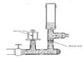
Figure 1A:Hydraulic Ram Pump
-
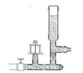
Figure 1B:Hydraulic Ram Pump
-
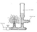
Figure 1C:Hydraulic Ram Pump
-
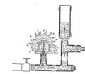
Figure 1D:Hydraulic Ram Pump


Figure 1 illustrates the hydraulic ram; initially the impulse valve (or waste valve since it is the nonpumped water exit) will be open under gravity (or in some designs it is held open by a light spring). The water will then flow down the drive pipe (through a strainer) from the water source. As the flow accelerates, the hydraulic pressure under the impulse valve and the static pressure in the body of the hydram will increase(Figure 1B) until the resulting forces overcome the weight of the impulse valve and start to close it. As soon as the valve aperture decreases, the water pressure in the hydram body builds up rapidly and slams the impulse valve shut. The moving column of water in the drive pipe is no longer able to exit via the impulse valve so its velocity must suddenly decrease; this continues to cause a considerable rise of pressure which forces open the delivery valve to the air-chamber.
Once the pressure exceeds the static delivery head, water will be forced up the delivery pipe. Air trapped in the air chamber is simultaneously compressed to a pressure exceeding the delivery pressure. Eventually the column of water in the drive pipe comes to a halt and the static pressure in the casing then falls to near the supply head pressure. The delivery valve will then close, when the pressure in the air chamber exceeds that in the casing. Water will continue to be delivered after the delivery valve has closed until the compressed air in the air chamber has expanded to a pressure equal to the delivery head. A check valve is included in the delivery pipe to prevent return flow. When the delivery valve closes, the reduced pressure in the hydram body will allow the impulse valve to drop under its own weight, thereby letting the cycle start all over again. Most hydrams operate at 30-100 cycles a minute.
The air chamber is a vital component. It may improve the efficiency of the process by allowing delivery to continue after the delivery valve has closed. It is also essential to cushion the shocks that would otherwise occur due to the incompressible nature of water. If the air chamber fills with water completely, not only does performance suffer, but the hydram body, the drive pipe or the air chamber itself can be fractured by the resulting water hammer. Since water can dissolve air, especially under pressure, there is a tendency for the air in the chamber to be depleted by being carried away with the delivery flow. Different hydram designs overcome this problem in different ways. The most simple solution requires the user to stop the hydram occasionally and drain the air chamber by opening two taps, one to admit air and the other to release water. Another method on more sophisticated hydrams is to include a snifting valve which automatically allows air to be drawn into the base of the air chamber when the water pressure momentarily drops below atmospheric pressure. It is important with such units to make an occasional check to see that the snifting valve has not become clogged with dirt and is working properly.
Engineering equations
Bernoulli's Equation
[2]

where
p= pressure
gamma= specific weight of water
v= velocity
z= height
Equation2:Flow in a Pipe[2]
where
Q= Flow Rate (m3/s)
v= Average water velocity in channel (m/s)
A= Cross-sectional area of water in channel (m2)

Equation 3:Head Loss[2]
where
hLf= head loss (m)
f= friction factor
g= gravity
Q= Flow Rate (m3/s)
L= Length of Pipe
D= Diameter of Pipe

Equation 4:Minor Head Losses[2]
where
hL(minor)=(= head loss (m)
K= Minor Loss Coefficient
g= gravity
Q= Flow Rate (m3/s)
D= Diameter of Pipe

Equation 5:

Implementation
Construction
Necessary Data: Once this data is collected a Ram Pump may be ordered or constructed.
1. Elevation change between source and pump (vertical fall)
2. Elevation change between pump and delivery site (vertical lift)
3. Amount of available water at source (Q input)
4. Minimum daily water needed at delivery site (Q outlet)
5. Distance from source to pump (drive pipe length)
6. Distance from pump to delivery site (delivery pipe length)

2.Excess Water Valve
3.Delivery Pipe
4.Impulse Valve
5.Delivery Valve
6.Pressure Vessel
[4]
1.Drive Pipe - Heavy gauge galvanised steel or cast iron is best. Burying prevents tampering by animals or people.[5] Normally the length of the drive pipe should be around three to seven times the supply head. Ideally the drive pipe should have a length of at least 100 times its own diameter. The drive pipe must generally be straight; any bends will not only cause losses of efficiency, but will result in strong fluctuating sideways forces on the pipe which can cause it to break loose.
2.Excess Water Valve - The cycling of the hydram is timed by the characteristic of the waste valve. Normally it can be weighted or pre-tensioned by an adjustable spring, and an adjustable screwed stop is generally provided which will allow the maximum opening to be varied. The efficiency, which dictates how much water will be delivered from a given drive flow, is critically influenced by the valve setting. This is because if the waste valve stays open too long, a smaller proportion of the throughput water is pumped, so the efficiency is reduced, but if it closes too readily, then the pressure will not build up for long enough in the hydram body, so again less water will be delivered. There is often an adjustable bolt which limits the opening of the valve to a predetermined amount which allows the device to be turned to optimize its performance. A skilled installer should be able to adjust the waste valve on site to obtain optimum performance.
3.Delivery Pipe - The delivery pipe can be made from any material capable of carrying the pressure of water leading to the delivery tank. In all except very high head applications, plastic pipe can be considered; with high heads, the lower end of the delivery line might be better as steel pipe. The diameter of the delivery line needs to allow for avoiding excessive pipe friction in relation to the flow rates envisaged and the distance the water is to be conveyed. It is recommended that a hand-valve or check-valve (non-return valve) should be fitted in the delivery line near the outlet from the hydram, so that the delivery line does not have to be drained if the hydram is stopped for adjustment or any other reason. This will also minimise any back flow past the delivery valve in the air chamber and improve efficiency.
4.Impulse Valve - There are a number of types impulse valves that may be used. The weighted-bolt-impulse valve is durable, easy to maintain, and the principles are easy enough for anyone to understand. Less weight means there will be a quicker stroke and less water pumped. More weight means slower strokes and more water pumped.
5.Delivery Valve - Also known as a check valveW. Only allows fluid to travel one direction. Types of check valves include: ball, swinging, diaphragm, lift-check.
6.Pressure Vessel - A large surge in pressue from the water compresses the air inside the Pressue Vessel. This surge in pressure is known as the known as the water hammer effectW[6]
Water Source - Typically stream or spring. Must have adequate flow rate. Higher elevation is better(more head). Must be able to measure flow rate. For smaller flows one may contain water using a dam or containment area. [5]For larger flows a weirW may be used. It is necessary to prevent dirt and debris from entering the pump and drive pipe. Grates, Filters and often times a supply tank or sediment tank is used.
Ram Housing - A security cover or housing may be prefered to prevent exterior damage or theft. The hydram body requires to be firmly bolted to a concrete foundation, as the beats of its action apply a significant shock load. The hydram should be located so that the waste valve is always located above flood water level, as the device will cease to function if the waste valve becomes submerged.
Reservoir Tank - A storage tank is usually included at the top of the delivery pipe to allow water to be drawn in variable amounts as needed.
Multiple Hydrams - Where greater capacity is needed, it is common practice to install several hydrams in parallel. This allows a choice of how many to operate at any one time so it can cater for variable supply flows or variable demand. The size and length of the drive pipe must be in proportion to the working head from which the ram operates. Also, the drive pipe carries severe internal shock loads due to water hammer, and therefore normally should be constructed from good quality steel water pipe.
Design considerations

Hydrams are mostly intended for water supply duties, in hilly or mountainous areas, requiring small flow rates delivered to high heads. They are less commonly used for irrigation purposes, where the higher flow rates required will usually demand the use of larger sizes of hydram having 6-inch or 4-inch drive pipes.[7] Manufacturers usually describe the size of a hydram by the supply and delivery pipe diameters (generally given in inches even in metric countries because of the common use of inch sizes for pipe diameters); eg a 6 x 3 hydram has a 6-inch diameter drive pipe and a 3-inch diameter delivery pipe.
Traditional hydram designs, such as in Figure 3, developed a century ago in Europe, are extremely robust. They tend to be made from heavy castings and have been known to function reliably for 50 years or more. However, although a number of such designs are still manufactured in Europe and the USA in small numbers, they are relatively expensive, although generally speaking the drive-pipe, delivery pipe and civil workings will be significantly more expensive than even the heaviest types of hydram.
Lighter designs, fabricated using a welded sheet steel construction, were developed first in Japan and are now in production in other parts of SE Asia including Taiwan and Thailand. These are cheaper, but only likely to last a decade or so as they are made from thinner material which will eventually corrode. Nevertheless they offer good value for money and are likely to perform reliably.

Some simple designs that can be improvised from pipe fittings have also been developed by aid agencies (Figure 4), and some interesting versions have also been quite crudely improvised using scrap materials, such as a unit which is being produced in some numbers in southern Laos from materials salvaged from bombed bridges and using old propane cylinders for the air chamber. Needless to say, such devices are very low in cost but the pipes in the end cost considerably more than the hydram. They are not always as reliable as traditional designs, but are usually acceptably reliable with failures separated by many months rather than days, and are easy to repair when they fail.
Cost
The costs of hydrams can range from under $100 for small "do it yourself" using local materials or close to $60,000 for larger commercial pumps. While the commercial pumps are more expensive they can handle the constant abuse associated with the hammer effect and high pressures. While the initial investment for a pump and the corresponding system may be seem high there are no fuel costs and low maintenance costs associated with hydrams.
$120 Homemade Hydraulic ram pump by Clemson Cooperative Extension [8]
A ram pump to supply a community of 300 people in the Philippines costs between $4,000-$5,000 [9]
Ram Pumps by Green & Carter with RAM sizes varying from 1-1/4 - 8 cost between $2,658 - $58,679 respectively.
Considerations for developing communities
Reliable, easy to repair. Train local technician.
Issues
Maintenance
Rams Pumps are known for continuously running while having minimal maintenance. This is largely because there are only a few moving parts. The available materials and proximity of a technician should be taken into account when selecting the type of pump. If there is a local person who has the ability to make repair and check the functionality frequently it may be best to build a ram pump using cheap local materials. If there is limited availability of a technician, a commercial pump may be preferable.[Hydraulic Ram Pump Manual] If clean water is used maintenance is only required after several years.[10]
Symptoms and possible causes for malfunction
Adaptation from USE OF HYDRAULIC RAMS IN NEPAL - A Guide to Manufacturing and Installation
(Book available free of charge from UNICEF Box 1187 Kathmandu, Nepal)[11]
1. Loud, metallic banging from pump
No Air in the chamber. Pump should be stopped and air chamber drained of water for maintenance. Check for air leaks.
2. Impulse valve does not work/Check for debris.
Check impulse valve on seating, should be able to move freely.
3. Impulse valve is intermittent
Often indicates air in drive pipe. Check to make sure drive pipe mouth is submerged by water. Drain any trapped air.
4. Pump is operating, but no water at delivery site
Make sure delivery gate valve is open and there is no obstruction or air blockage.
5. Impulse valve stays open
Not enough water in drive pipe, too weight on impulse valve, or delivery valve issue.
6. Uneven strokes or knocking
Leak/air in drive pipe. Not enough water above drive pipe.
Alternatives
Other sustainable pump alternatives include:
Gravity PumpsW, Hand Pump W,Animal Driven Pump, Solar Pump, Wind PumpW, Treadle PumpW, Rope Pump
Performance characteristics
Table 1 indicates estimated performance for typical 2-inch x 1 inch and 4-inch x 2-inch and 6-inch x 3-inch commercial hydrams.
| Hydram size in inches | 2" X 1" | 4" X 2" | 6" X 3" | |||||||||
| Head Ratio | 5 | 10 | 15 | 20 | 5 | 10 | 15 | 20 | 5 | 10 | 15 | 20 |
| Driven flow (litres/sec) | 3.3 | 5.2 | 7.4 | 9.2 | 8.96 | 9.7 | 10 | 9.02 | 20.2 | 17.2 | 17.1 | 19.3 |
| Delivery (m³/day) | 55 | 38 | 22 | 17 | 94 | 51 | 35 | 23 | 216 | 101 | 69 | 50 |
Table 1: Estimated performance of hydrams
Further information
References
- ↑ 1.0 1.1 http://www.greenandcarter.com/main/about_us.htm
- ↑ 2.0 2.1 2.2 2.3 Mihelcic, J. R., Fry, L. M., Myre, E. A., Phillips, L. D., & Barkdoll, B. D. (2009). Field guide to environmental engineering for development workers: Water, sanitation, and indoor air. Reston, VA: American Society of Civil Engineers.
- ↑ http://www.lifewater.org/resources/rws4/rws4d5.htm
- ↑ http://www.akvo.org/wiki/index.php/Hydraulic_Ram_pump
- ↑ 5.0 5.1 http://www.greenandcarter.com/main/service/installation.htm
- ↑ A. Tessema, "HYDRAULIC RAM PUMP SYSTEM DESIGN AND APPLICATION ," ESME 5th Annual Conference on Manufacturing and Process Industry, Vol. , no. , pp. , September 2000.[]. ESME:http://www.africantechnologyforum.com/ESME/hydram2/HydRam2.htm.
- ↑ B. W. Young, "Generic design of ram pumps," Proceedings of the Institution of Mechanical Engineers, vol. 212, pp. 117-117, 1998.
- ↑ http://virtual.clemson.edu/groups/irrig/Equip/ram.htm
- ↑ http://www.ashden.org/water_pumps
- ↑ Green. Carter. (2002). Hydraulic ram leaflet. Retrieved from http://www. Greenandcarter.com/main/rampumpleaflet.htm.
- ↑ M. Silver, Use of hydraulic rams in Nepal: A guide to manufacturing and installation, Edition of book, : UNICEF, 1977,
Other references:
- 1st Initial. Practical action, "Hydraulic ram pumps," Practical Action Technical Briefs, Vol. , no. , pp. , 02 february 2002.[]. :http://practicalaction.org/hydraulic-ram-pumps.
- B. W. Young, "DESIGN OF HYDRAULIC RAM PUMP SYSTEMS," Proceedings of the Institution of Mechanical Engineers Part a-Journal of Power and Energy, vol. 209, pp. 313-322, 1995.
- B. W. Young, "Generic design of ram pumps," Proceedings of the Institution of Mechanical Engineers, vol. 212, pp. 117-117, 1998.
- E. J. Schiller and P. Kahangire, "ANALYSIS AND COMPUTERIZED MODEL OF THE AUTOMATIC HYDRAULIC RAM PUMP," Canadian Journal of Civil Engineering, vol. 11, pp. 743-750, 1984.
- "High pressure ram pump development," World Pumps, vol. 1996, pp. 15-16, 1996.
- Hofkes and Visscher 'Renewable Energy Sources for Rural Water Supply in Developing Countries' - International Reference Centre for Community Water Supply and Sanitation, The Hague, The Netherlands - 1986.
- "Hydraulic ram pumps," Appropriate Technology, vol. 29, pp. 30-33, 2002.
- Iversen H W 'An Analysis of the Hydraulic Ram' - Journal of Fluids Engineering, Transactions of the American Society of Mechanical Engineers - June 1975.
- J. A. Kypuros and R. G. Longoria, "Model Synthesis for Design of Switched Systems Using a Variable Structure System Formulation," Journal of Dynamic Systems, Measurement, and Control, vol. 125, pp. 618-629, 2003.
- Jeffery, T D, Thomas T H, Smith A V, Glover, P B, Fountain P D 'Hydraulic Ram Pumps: A guide to ram pump water supply systems' – ITDG Publishing, 1992
- Kindel E W 'A Hydraulic Ram for Village Use' - Volunteers in Technical Assistance, Arlington, VA, USA - 1970 and 1975.
- M. D.F, "Technical feasibility of wavepower for seawater desalination using the hydro-ram (Hydram)," Desalination, vol. 153, pp. 287-293, 2003.
- "Ram pumps," World Pumps, vol. 1999, p. 55, 1999.
- "Ram pumps take the drudgery out of sludge transfer," World Pumps, vol. 1999, pp. 18-19, 1999.
- S. Watt, A manual on the hydraulic ram for pumping water, 3rd ed., London: Intermediate Technology Publications Ltd., 1977, p. .
- V. Filipan, Z. Virag, and A. Bergant, "Mathematical modelling of a hydraulic ram pump system," Strojniski Vestnik-Journal of Mechanical Engineering, vol. 49, pp. 137-149, 2003.
- W. P. James, "Hydropower valve: a new application for an old device," Journal American Water Works Association, vol. 90, pp. 74-79, Jul 1998.
19. Y. Altintas and A. J. Lane, "Design of an electro-hydraulic CNC press brake," International Journal of Machine Tools & Manufacture, vol. 37, pp. 45-59, Jan 1997.
Suppliers
Note: This is a selective list of supplies and does not imply ITDG endorsement.
Green and Carter Rams
Vulcan Works
Ashbrittle
Wellington
Somerset
TA21 0LQ.
United Kingdom
Tel: +44 (0)1823 672365
John Blake Ltd.
P.O.Box 43
Royal Works
Atlas Street
Clayton Le Moors
Lancashire, BB5 5LP
United Kingdom
Tel: 01254 235441
Fax: 01254 382899
E-mail: sales@allspeeds.co.uk
Useful addresses
Development Technology Unit (DTU)
School of Engineering
University of Warwick
Coventry CV4 7AL
United Kingdom
Tel: +44 (0)1203 522339
Fax: +44 (0)1203 418922
E-mail: dgr@eng.warwick.ac.uk
Website: http://www.eng.warwick.ac.uk/DTU
Development Technology Unit who has carried out a lot of research into simplifying the construction of hydraulic ram pumps. The DTU is a research unit within the School of Engineering at the University of Warwick in the UK. The aim of the DTU is to research and promote appropriate technologies for application in Developing Countries.
WOT - Werkgroep Ontwikkelingstechnieken
Working Group on Development Techniques
Vrijhof 205/206
P.O.Box 217
7500 AE Enschede
The Netherlands
Tel: +31 53 489 3845
Fax: +31 53 489 2671
E-mail: wot@tdg.utwente.nl
http://www.wot.utwente.nl/
WOT is a non-profit organization working in the field of small scale sustainable energy, based at the University of Twente.
Raintree-Foundation
Research and Development of MERIBAH Ram Pumps
10120 Bangkok
Thailand
E-mail:info@raintree-foundation.org
       ts@meribah-ram-pump.com
http://www.raintree-foundation.org
http://www.meribah-ram-pump.com
One part from the raintree-foundation works with appropriate technologies. They cooperate with MERIBAH which provides research and development of new generation ram pump and snail pumps.
Template:Attrib PATB
Template:Includes content from