Background: Community 3-D Printer & Workshop[edit | edit source]
This project was initiated through an Engineering 305 course at Cal Poly Humboldt. Andreas Geyer and Justin Tuttle were assigned to this projectRepRap Prusa Mendel (Iteration II) built by students in Engineering 305 (Appropriate Technology) at Cal Poly Humboldt out of interest. Both Andreas and Justin are HSU students; Chemistry and Psychology majors respectively. The project had guidance from Lonny Grafman and many other people through The Link and Propulsion. Shawn Dean of OWnS 3D Printing also was a mentor and offered assistance with the project.
Our groups goal was to successfully build and present a working 3D printer to people by the end of the semester. This project was unique in the time required and the materials that were needed for the construction. The project is not initially an example of Appropriate Technology. The project is more of a foundation that can provide ease for future projects and the future design of more Appropriate Technology 3D printers. Challenges and difficulties with the build will be listed for future users and builders can reference for their construction. Our Appropedia page will try to provide documentation towards our construction of our 3D Printer and an overview of the basic components of a 3D Printer.
3-D printing is a rising technology that has been around for at least 30 plus years. As it has been subsequently transcending down from industrial/manufacturing market to the average hobbyists, whom have innovated engineering designs and functionality of what 3-D Printers are now capable of, the resurgence of the new implications for 3-D Printers has been noted as a Revolution within itself. The resurgences' of 3-D printing technology is mainly due to the popular notion of "open source information". This ideal has been popularized by many rising companies that believe that sharing information, and knowledge is a way to get faster solutions and new inventions to ongoing issues. We are certainly not the first to take part in open source 3-D Printing (Open source 3-D printing of OSAT).Open source 3-D printing of OSAT has an emphasis on applying the open source use of 3-D Printers for Appropriate Technology issues at hand. The concept of 3-D Printing is simple, three dimensional objects can be created from digital CAD models. These printers extrude different materials (i.e.plastics,wood) in order to create different physical 3-D objects. Being able to create these items rapidly allows for very easy prototyping which will hopefully attract more market into Humboldt County. Many individuals have creative ideas, but are unable to put these ideas into the market.
3-D Printing is a process that contains many different subcategories to make a complete working machine and system: For example, if we work backward from the printed object; there is something that has to extrude that plastic, then a system of motors that make a perfect coordinate system to move that extruder, then an electrical system to tell the motors to move in unison, when to start and stop. Followed by an electrical connection from the motors to an electrical system then to a computer, which contains a software or firmware program (often custom made) to control the conversion of the design to an electrical output. Then finally the digital CAD (computer aided design) file that the software/firmware receives to start the whole process. As you can see this system has many components which all need to work correctly to make a 3D printer a working reality.
For information about how the 3D printers components all work together; please refer to the "Breakdown of our 3D Printer" section for:
Hosting a workshop takes time and effort. There are many things that can go wrong in a workshop and this literature review will hopefully refrain us from these wrong doings. Time and place are a huge factor into holding a good workshop where people show up. As for a place we are restricted to The Link, because that is where we will be permanently employing the 3D printer. As for a time, it has been shown that Saturdays noon or Sunday afternoon are the best time for people[1] A good workshop requires beverages and food to keep people happy.[2] We plan on having free water and depending on costs some snack platters. Keeping people entertained is the major factor of how much people will learn from the workshop.[3] With this we will create an interesting presentation and throw some humor into it so people don't get too bored. Studies have shown that community involvement with the workshop has had the most success.[4]An idea we had to implement this is to have groups work together on a CAD drawing for an allotted amount of time and seeing which group creates the most creative image and printing it out.
This chart of criteria will be used in assessing which 3-D printer will work best with the community and save the most money for the client. Criteria were chosen with respect to the clients goals and the ease of working for the community. The scale (1-10) assumes that 1 is the worst situation and 10 is the best situation (i.e. a pricing for 10 is extremely cheap.) Each criterion is weighted for its importance/value of the client and the project team. The Overall Printer Total represents each criterion's weighted number multiplied by each models speculated total, resulting in an overall score for each printer.
Criteria:
Constraints:
Weight per Constraint:
Prusa
Prusa Total:
RepRap Huxley
Huxley Total:
RepRapPro Mendel
Pro Mendal Total:
Price: Hardware
Must be within affordable range of the client.
10
8
80
6
60
6
60
Price: 3-D Printed parts
Must be within affordable range of the client.
10
9
90
10
100
9
90
Open Source Community
Must have the documentation and contain enough "open" information for a client to research and find themselves.
8
10
80
5
40
6
48
Ease of Construction
Must be within capabilities and time allocated.
7
8
56
8
56
6
42
Ease of learning
Must be relatively easy to use for members of the community
9
8
72
7
63
7
63
Special Features
Weighted on others features
3
8
24
7
21
8
24
Weighted Total:
402/470
340/470
327/470
Printer Overall Total:
8.5
7.2
6.9
Model:
Price: Hardware
Price: Printed Parts
Percentage of Printed Parts
Accessablility of Open Source:
Ease of Construction:
Special Features:
Prusa (Iteration 2)
Extensive list of [Full Models] and [Kit Models] available. Along with a list of merchants for majority of parts required for the build. For actual [Kit] and [Full Price] numbers refer to Buyer's Guide: http://reprap.org/wiki/Prusa_Buyers_Guide. *Most companies are in other countries. This website seems ot be one of the most reliable http://reprappro.com/Mendel. It is also out of country.
Printed parts can be purchased in [Kit] form.
Complete list and quantity of each part required for construction is provided.
Contains a considerable amount of information provided online through the RepRap wiki page.
Numbered specific instructions with multiple Youtube videos to describe each step and part of the build.
Ease of Construction and Maximized Documented Information
RepRapPro Huxley
Same list as above. Smaller amount of websites that offer this model. *Most companies are in other countries. Refer to Buyer's Guide: http://reprap.org/wiki/Prusa_Buyers_Guide. This website seems to be one of the most reliable http://reprappro.com/Mendel for buying information. This company is out of country.
Printed parts can be purchased in [Kit] form.. [One complete set of polylactic acid (PLA) printed RepRapPro Huxley parts has a mass of about 260 grams.] Approx. Cost of printed parts would be around $10-15, if printed on personal printer.
Complete list and quantity of each part required for construction is provided.
Contains a considerable amount of information provided online through the RepRap wiki page.
Specific documentation, including pictures, and specific assembly of each part of construction. Also has a well documented webForum.
Small and Portable
RepRapPro Mendel
Same list as above. Smaller amount of websites that offer this model. *Most companies are in other countries. Refer to Buyer's Guide: http://reprap.org/wiki/Prusa_Buyers_Guide. This website seems to be one of the most reliable http://reprappro.com/Mendel for buying information. This company is out of country.
Printed parts can be purchased in [Kit] form.
Complete list and quantity of each part required for construction is provided though Thingiverse.com.
Contains a considerable amount of information provided online through the RepRap wiki page. Some more documentation on other provided websites.
Detailed instructions; design is mostly based off of RepRap Prusa Mendel with a lot of alterations. Main point of this model is being able to print multiable colors. Con is that multi-color = more complicated construction and possibly more/ modified software.
This table lists certain companies pricing for either a complete printer kit with plastic parts printed or without plastic parts. This table should help in the decision process of accessing which company to choose in buying the Prusa Mendel model 3-D Printer. The (3) companies were chosen by the reputableness and reviews of their company and websites. Each company also received an email asking for a Student/University discount to help our project become a reality.3D-printing.com.au was the only company that offered a University discount. Keep this option in mind when purchasing your printer.
After our group decided on the Prusa Mendel we purchased it from www.a2aprinter.com. The plastic parts were bought from www.ebay.com, there are many providers when buying the plastic parts. One consideration is making sure that your hardware/electronics and the plastic parts are designed for the same model of printer. Because of the open-source design of these projects a lot of updates can happen frequently.
When trying to figure out company to decide on for your printer. Try using the RepRap Wiki page [citation] as a reference. They list many companies on their page. One of the main reasons this is a great resource is they have forum/discussion conversations about the companies of which you can cross-reference and see which one works for you best.
Also make note that each company is selling a different type of printer and model with different updates. One of the biggest challenges for the construction phase of the project was constructing a Prusa Mendel (Iteration 1) hardware and having plastic parts that were made for the (Iteration 2). When shopping for a company make sure to get as much specs as possible:
1) What type and model of electronics are included?
2) What make and model edition is the printer?
3) Are the electronics wired together?
4) Do I need to purchase anything else before assembly?
This timeline contains a breakdown of different stages that need to be completed for our project. Different stages are allocated longer or shorter amounts of time depending on how challenging the task is perceived to be.[MORE]
Although our proposed timeline looks great this is not a true story line for this project. Our first delay was buying the actual printer. This project is very different than other Appropriate Technology projects by means of money. Unfortunately, this project cost almost $700 which is not very appropriate. There was much time delegated of how the printer was going to be purchased.
NOTE: Figure how your project is going to be funded. Based off of our research and construction done for this project. I definitely believe that this printer could be made for less and perhaps without going through a company. If the proper research is done, all materials and BOM are provided FREE online.
Our next delay came in our delivered package. Upon the first day of construction we had noticed that the 8 threaded rods needed for the frame construction were not included. Once talking to a2aprinting the mistake was noticed and the rods were sent 1 week from that date.
NOTE: For future reference of making the Prusa Mendel; depending on what part you are missing or what stores you have access to the parts missing can be picked up at a local hardware store to limit time delay.
After building the basic frame of the printer we had noticed that some of the parts were not matching up with our biuld. It was recognized that the printer from a2aprinting was a Prusa Mendel (Iteration 1) and the plastic parts were from Prusa Mendel (Iteration 2). This had a large delay in construction were many plastic parts needed to be drilled to fit certain parts of the build. I hope to have a detailed listing of all the extra modifications that were made. The main issue with the parts and hardware being different is when it came to the Extruder. The hardware was present to make the build but the design measurements were made for a different type of Extruder system. Modifications were made to adjust for the issue. Please look at Extruder in Breakdown of Our 3D Printer.
NOTE: Do your research! Open source means the information is out there, so make sure your ducks are lined up.
As mentioned throughout the page, our company did not provide wire connectors for the any of the wiring components. Making the wiring stage a lot longer although extremely educational. Figuring out how to wire the motors in what order was one of the most challenging aspects in this section. Not a lot of open source information was provided if your system didnt already have wire connectors provided. Another challenge was wiring the 2 (Z Axis) motors in parallel, although with a few online searches the issue was easily fixed.
NOTE: If your buying a kit ask about the electronics! What type, model? Is your board going to be wired. Do you need to buy wire connectors?
This section is for understanding the 3-D printer on a component scale. The 7 sections should provide some information on each major contributor for the 3-D printer system. This will also provide the background information required for our team to build our own printer. Majority of this information was contrived from open-source websites; and in the same nature, this section is subject to be modified as more information is provided and understood. This section also provides a detailed listing of how each part of the construction worked or didnt work for our project along with modifications, pictures and video of how we built our printer.
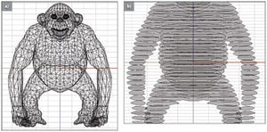
[5]CAD files or computer aided design files are essentially the sketch board of the design process. Allowing the creator to have control of all designs, maximizing creation, modification, and analyzing the project at hand. These designs are usually in a 3D model and in a vector format of viewing (i.e.very sharp and crisp drawing lines). These designs allow the creator to include processes, dimensions, and materials, allowing the design to be completely analyzed before it is physically produced.STL Files:[6]STL files or STereoLithography is a type of CAD file format. This file format is very common in the 3D Printing world. It is a more simplistic file type than CAD files, limited by its lack of use of color, and textures. STL files use a triangular modeling system that breaks down the surface of the object into three-dimensional Cartesian Coordinate System[7].
From the design stage to actual print. Designed by Justin Tuttle with Alibre Design and printed with a Makerbot using PLA plastic.
The design on the left was created by Justin Tuttle for a local company called "The Link". This is their logo design. The program that was used to create this was called Alibre Design [CITATION]. Alibre Design was easy to use and design with. In order to create this logo a 30-Day trial was used for designing. For the designing aspect of the project it doesnt really matter what kind of program you use. The most important aspect is that the file format is the right kind.
Good News:
Alibre Design is relatively cheap compared to a lot of other design programs. They offer an awesome 30-Day trial period with a lot of online resources for figuring things out and a representative gave us a call and an email every 10 days when using the program.
Bad News:
Alibre Design at this moment doesn't allow you to upload an STL file into their program. When talking to the representative, he mentioned that they are merging companies and hopefully this will be an addition to there newer program updates.
When looking for a program/software to use consider the first option; FREE. There is software out there that is free; it is called FreeCAD. [citation]. This software has great information resources, although it is not for the lay designer. The more experience that you have with design software the better otherwise its a bit tricky to get started. There are many other software providers out there and its important to get started with the right one. Some software is extremely complicated to work with and some is really intuitive, depends on your experience and time. Might not want to spend $1000's of dollars on software when you only need to make simpler designs at first. Here are some CAD programs that we came across during this project:
[8] The software that each 3D printer system uses varies by very specific modifications and by the company creating it. In the 3D printer world most software either comes with the purchased package, or is easily downloadable on a website , RepRap on your computer. This software acts as a mediator to convert the CAD or STL files into actual motor movement by the 3D printer .CAM (computer aided manufacturing)[9] software uses the STL files to convert them into G-Code. G-Code is the 'machine friendly' language that communicates the software to the 3D printer. To take the STL file and convert it into G-Code a slicer,[10] mediator software,is often used. Imagine a virtual deli-slicer cutting each layer of the 3D model into hundreds of slices then figuring out what is the simplest, fastest, and least amount of plastic that can be used to print this layer. This process occurs hundreds of times until each layer of the 3D model has been converted into G-Code. The G-Code is then sent to a G-Code interpreter,[11] which sends our 'machine friendly' language to the actual motors of the 3D printer to be printed. Hundreds of layers converted from a triangulated 3D model into interpreted sliced G-Code, then sent to the Micro-Controller firmware. google images
For this section all we did was download the appropriate software. How the programs actually does this is by complex algorithms. All we had to do was install the program and make sure that it was working properly with the rest of the software downloads.
Here are some websites that are G-Code software. One thing to look out for is different software gives you different abilities as far as control of your printer and specific settings that you might want to do. Some of the software's that have been out longer have been able to work out the bugs and tweak for the use of 3D printers.
[12]Firmware as the name implies is the memory or program data stored onto a physical device, usually a computer board or chip. The G-Code's, that the software creates goes to a Firmware (i.eMicro-chip or Micro-controller )and is stored there. Typically once the coded information is on the physical device it cannot be manipulated unless you go back to the software and make modifications to the 3-D model. The firmware data contains all the coded information of the print along with the instructions of how to print it.
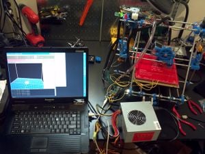
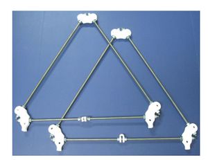
Graphing how the system works with the printer and the computer together.Pronterface software. You can see that the Pronterface is about to print the foundations stands of a RepRap Prusa Mendel.
For our project the firmware was already downloaded onto the aruduino 2560 system. When you get to the point of plugging in your electronics to the computer, you should be prompted for Arduino 2560 install of the driver. Basically for the software installs we went to the website listed below and installed everything that it told us to including: While this looks like many steps it is.
Complete Directions for Software Downloads:
1 Install Python 2.7.x
2 Install PYSerial
3 Install PYReadline
4 Install wxPython
5 Install Arduino Integrated Development Environment
One of the most resourcful things that we came across in our build was this website. Mendelcraft.com has a very thorough listing of all the software thats needs to be downloaded before you connect the printer to your computer. It has step by stepp instructions of electronics and building. I would DEFINITELY use this as a resource for future builds.
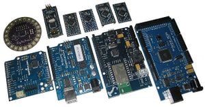
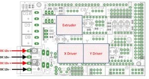
[13] The electrical controller of the 3-D Printer is the Micro-controller mentioned above. The make and type of Micro-controller's used varies wider than the different models of 3-D Printers on the market. Micro-Controllers are not necessarily just designed for 3-D Printer use. Their implications and applications are far and wide. With Arduino[14] being one of the most popular Micro-Controller electronics out there. Arduino just like the RepRap prides itself on its availability of knowledge through open source information..[15] Making Arduino one of the top contenders of its industry. Because of the Arduino Movement, and the spread of open source documentation many new electronics, devices and inventions have been created using their platform. The Micro-Controller is connected via USB to the computer where the data transfer and communication from the software occurs. The Micro-Controller can be housed somewhere on the actual 3-D Printer itself or close by. Typically you want to reduce the amount of wiring necessary and the possibility of tangling of the wires. Sense each 3-D Printer model is different, efficiency is maximized however possible.Just some of the varying models of Arduino Micro-Controllers. Each with their own specifically designed functions and use. google imagesShowing X,Y, and Z for where you want to solder your drivers onto the RAMP board.
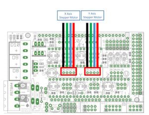
This is another diagram that we used to wire our RAMP board. *NOTE: The motor wiring connection are different in this diagram than the configuration that we used.
The Micro-controller that came with our Prusa Mendel was an Arduino-MEGA. This micro-controller came "electronically-sound", we did not have to wire anything together on the Arduino. With our Arduino came a shield (a top attachment piece) also known as a RAMPs (Rep Rap Arduino Mega Pololu Shield)[citation]. This RAMP came with 4 drivers that needed to soldered onto the RAMP board. These drivers control the motors from the printer to the shield to the Arduino then to the computer. All of the motors and anything that is run from electricity will be connected to your RAMP. For our project we used the RAMP 1.4 which is the newest edition of board designed for Rep Rap use. For our project nothing came pre-wired.
1)The drivers were first soldering into the RAMP board.
2)Each of 5 motors was then soldered to the board.
NOTE: Our company did not provide wire connectors. This would have cut electronics constructions down by many days! Ask your company if they are using wire connectors.
IMPORTANT:Figure out whether your provider is giving you a RAMP or not (should come with). If so, what edition is the RAMP (1.2,1.3,1.4. This makes a difference of how much soldering you might have to do. Older models have more open-resource information. Our system came with nothing wiring together! Open source information seemed to be lacking with this section of the build. There are some diagrams about that contain the wiring, although with out wire connectors for your board this can take a while.
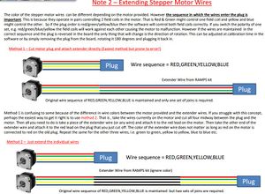
[16] The motor system is referring to the motors that are moving the three dimensional axis's (i.e. X,Y,Z ) of the printer. One important part to include in the process is that each companies and subsequent models of printers they provide are vastly different from the next. Some printers might only use 1 motor to get the job done while others can use 4. For the RepRap and a lot of similar models 3 is the typical amount of motors used. The type of motors that these printers use are called Stepper Motors.[17] Stepper motors are fairly common in the robotics and machines that are somewhat smaller; this is because of the size and torque capacities that these motors can supply."Stepper motors move a known interval for each pulse of power. These pulses of power are provided by a stepper driver and is referred to as a step. As each step moves the motor a known distance it makes them handy devices for repeatable positioning.".[18] Stepper motors can be broken down into two categories Unipolar and Bipolar motors. The intricacies of the differences in electronics will not be discussed here, although if you would like to find more information please refer to reference link below. Some of the first RepRap designs had electronics specifically made to power the stepper motors stepper motor driversDr. Iguana. The reason for this is because some of the Micro-Controllers used do not have the proper amount of power required to power all the motors at once. For this, often an additional circuity is added to preexisting Micro-Controllers and/or a stepper motor driver can be introduced. Make sure to identify your motor wire colors to tell what way your going to wire them to the board.Each wire color goes to a specific connector on the RAMP board. If the color are different than this image, reference the image on the right.
As mentioned in the Micro-controller section above, none of our motors contained wire connectors. This means that each motors 4 wires had to be soldered to the RAMP board. The motors that were provided from the company are NEMA 17 (long). These are very typical motors in the 3D printing world. They are the long ones compared to the NEMA 14 which are slightly shorter. Some of the plastic parts on the (X Axis) needed to drilled out to screw in the NEMA 17 motors into the (X Axis) mounts. Given that a lot of plastic parts needed to be drilled for our build this did not require too much energy. Our system came with 5 motors total: [1 (Y Axis)][1 (Z Axis)][2 (X Axis)][1 (Extruder)]. Since our motors did not have wire connectors each motor was manually wired to the RAMP board. Our motors had colors in order [RED,GREEN,YELLOW,BLUE]. The wiring was cross-referenced with online information about the proper way to solder them to the RAMP board [link]. The 2 stepper motors for the (Z Axis) were also not wired or mounted together. To do this the two (Z Axis) stepper motors were wired in parallel. Which motors were the (Z Axis) motors was arbitrary, all the motors were identical. Once the motors were decided, they were wired in parallel then connected to the RAMP board. An easy way to wire the motors in parallel was soldering the wires of the each motor that shared the same color.
IMPORTANT: Note whether your company is providing the motors for you. Double check which type they are to anticipate any wiring challenges. Ask if they will be providing wire connectors! Instead of 5 hours or wiring it will take 5 minutes. Although your motors may look the same there are dozens of stepper motor providers. If the motor seems the same and the color of the wires are the same then generally you could follow the wiring diagram you found. Ask if your Z motors are going to be wired together or not. If not you will have to will have to wire them in parallel of each other.
On the right is the Mechanical End-Stop with the typical pins used circled in red. On the left is the plastic RP End-Stop holders.
The End-Stops are essential a switch that tells the software that you have hit the end of the axis. There are 3 End-Stops, one for each axes (X,Y,Z). These End-Stops also help in the calibration part of the print. For example, the (X-Axis) which controls how close the extruder tip will get to the print bed is a very important sensor. This controls the overall thickness of each layer of plastic that is laid down. This switch must be calibrated before every print, to ensure the quality of the print.
This is the Mechanical End-Stop wiring diagram. Once again the polarity does not matter, although if connecting to (X) axis for example, it is best make sure the End-Stop is physically located on the (X) axis and not any other axis. This will make it easier for calibration/ editing of the software if needed.
The 3 End-Stop (switches) were provided with our purchased kit. The typically have 3 available pin wire connections. Depending on which type of Micro-Controller and or software you are using some are wired differently. With our printed parts came 3 plastic RP (reprap) End-stop holders, these are the mounts for the end-stops. Each End-Stop came with a 2 small screws and bolts to attach onto the RP End-Stop holder. When wiring your End-Stops you should see 3 pins as mentioned, labeled as (NC-NO-C) in this order. We soldered a wire from (NC) on the switch to the (S) on the RAMP board. Then we soldered a wire from the (C) connector to the (-) negative on the RAMP board.
There are also End-Stops called Opto End-Stops. These End-Stops a.k.a. Optical End-Stops send out a non-visible beam of light that when disrupted by the physical components of the machine will signal the machine to stop. This is a fancier option when building your machine, although some Micro-Controllers/Software might not be compatible, make sure to check before going this route. Also check the wiring configuration on your Micro-Controller to determine where your End-Stops will be wired to. When wiring our End-Stops there were 3 pin options on the Arduino, although the correct wiring only used 2 the (S) and (-), which were the (NC) and (C) on the physical End-Stop switch itself.IMPORTANT:The Mechanical End-Stops are not polarity specific when connecting them to the RAMP board.
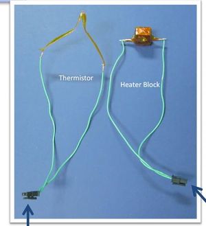
[19] The extruder is one of the final stages in this process. The extruder simply heats plastic (i.e. filament) into liquid format, by heating an electrical coil, so that it can be layered on top of itself to create the 3-D Model. The extruder is also controlled by Stepper Motors. There are a lot of different types of extruder's with individuals creating their own designs and modifications for what they would like. Some models of Printers have 2 extruders to print different colors (i.e. RepRapPro Mendel ).Notice that the heater wires through the heat block are wired at each end. For our construction of the extruder the heat block had two holes for two heat wires. These needed to be wiring in parallel of each other.
For our construction of the Extruder, it should noted that we obtained the (Iteration 2)plastic parts while having a Iteration 1 extruder. This made the construction slightly complicated. For the build of the extruder we followed the instruction listed off of the http://garyhodgson.com/reprap/wades-geared-extruder-visual-instructions/ website. This shows a pretty complete physical build process. For the wiring the thermistor and the hot end wires were attached onto the extruder via instruction for a Mix G1 extruder. This information for what type of extruder we had purchased was obtained from www.a2aprinters.com from which we bought the parts.
Watch out for the wiring of the extruder. The hot end heaters, usually two fat resistor looking wirers (NOT resistors though) will be put through the metal heat brick. Once they are placed within the metal heat brick there are wiring in parallel of each other. This basically means that each end of the wires are wired together then a third wire connected will then go to the control board. The thermistor will also be placed through the heat brick and each end will be a positive and negative connected to the control board.
IMPORTANT: The polarity of the extruder heaters and thermistor usually do not matter. Of course check your board and other information to make sure this is homologous for your microcontroller.
The construction of the frame should be the most straight forward part of the build. There are many diagrams out there to help for this. Depending on which model and plastic printed parts you have there will be slightly different ways to build the printer. Basic frame construction.
There are specific calibrations length of the frame that should be obtained during construction. This ensures quality prints.
For your build we found instruction through the www.reprap.com wiki page. Through this there is many different wiki pages that will aid in construction for which part of the build we were on. We used this website any some others for our construction of the frame. Through these different websites we were able to get the frame constructed.
[20] Finally, we get to the printed object. The object can be printed (extruded) using different types of plastic (filament). Acrylonitrile butadiene styrene (ABS), polycarbonate (PC), polylactic acid (PLA) are among the most popular platics used. Many of these plastics can be bought through online providers..[21] Another leading innovation has been set in motion within the last 1-2 years of creating your own printable plastic. For example, some of these plastics are the same plastics that would make up a Milk Jug (HDPE[22] ). Individuals in the community have started making simple machines that can breakdown different recyclable plastics and make them into a filament for printers to use. Companies such as Recyclebot & Filabot are some of first to arise..[23] These machines are still somewhat new, but are very promising in changing the way that people get their plastics. Making 3-D printing one step closer towards achieving an Appropriate Technology direction with using recycled plastics from your own street, home , or business as a sustainable model.
The thing that matters the most when actually printing the objects is the resolution that your getting from your prints. Some of the ways that you can check these things are:
1) Always calibrate the printer after every print
2) What type of plastic are you using (ABS, PLA) they melt at different temperatures.
3) Make sure that the extruder is at a constistant distance from your heatbed.
A series of modifications were made during the building and electronics part of this project. For future builders of 3DP's I will list the modifications made. These modifications are specifically made for the RepRap
TAKE PICTURES FOR THESE MODIFICATION!*
1) No Springs:
2) Arduino Troubleshooting:
3) Broken Parts:
4) Z-Axis(Negative Space Prevention):
5) Print Bed Wing Nut:
6) Molex Shield Connectors:
The electronics (wires/parts) that were with our package did not include Molex Connectors. Probably one of the most problematic situations of the whole project and easiest to fix. These molex connector are essential for the build, mostly because of the design of the RAMP shield is so small that it is very common to have a short when you wire everything up. If your electronics do not have these I would highly recommend getting them.
Where: You can find Molex connectors at a common electronics store or on www.sparkfun.com for (.45 cents). For this project we took some molex connectors that were not being used on the PC power supply. Then we found 2 more needed at a scrap yard for (.10 cents).
Our printer is in the finalization stage of assembly. Our constructions took most of our time because if any part wasn't done correctly the next part wouldn't work correctly. Especially when it came the electronics, each step soldered needed to be wired correctly or the board would short circuit and fry. With my lack of electronics experience I choose to take the electronics section slowly as to not jeopardize the whole project.
If you have any further questions or comments or something that I should include on the page, please message me and I will do so. If you want to discuss some the construction processes I would love to help someone out in the same situation, as I wish I had for this project.
Next steps are to make sure that this printer is working and can be working for future students and people interested in this technology. I would like to see a filabot or recyclebot. A machine that can take waste plastic material and reuse it to make the filament required to print objects. I would like to see other people use this machine to further there concepts and technology of what Appropraite Technology is. I would also like to use the 3D printer technology to use in a BioMedical realm to try and print cells of the human body. I would like to see this technology be used for the good and beneficial uses of humanity however someone might see it.
↑Klatt, Bruce. The Ultimate Training Workshop Handbook: A Comprehensive Guide to Leading Successful Workshops and Training Programs. McGraw Hill Professionals, 1999.
↑Sarkissian, Wendy and Bunjamin-Mau, Wiwik. SpeakOut: The Step-by-Step Guide to SpeakOuts and Community Workshops. Routledge, 2012
↑Jolles, Robert S. How to Run Seminars & Workshops: Presentation Skills for Consultants, Trainers and Teachers. John Wiley & Sons, 2011.
↑Corrigan, Dorothy D. Workbook for a Successful Workshop. American Library Trustee Association, 1967