This tutorial shows you how to perform a FEA (Finite Element Analysis) for standard ASTM D638-14 Type IV in FreeCAD. See also ; FEA compression in FreeCAD
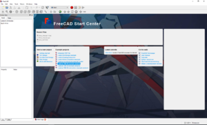
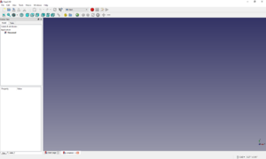
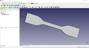
Fig 1: Freecad Open SheetFig 2: Freecad New Sheet Open FreeCAD. Click on the ‘File’ tab and select ‘New’.
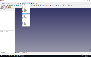
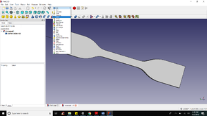
Fig 3: Part Selection Drop Down Menu Click on the drop-down box where it says ‘Start’ and select ‘Part’.
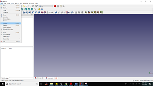
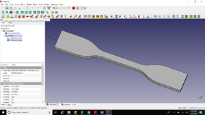
Now click on the file tab and select import option to use file with differenct format. FreeCad allows you to use various file type. FOr this example we will be using IGES file. Find the file in you system and upload. You can rotate the object with help of scroll button on the mouse. Fig 4: Importing IGES fileFig 5: Imported file window
Click on the drop-down box again and select ‘FEM’. This will turn on the analysis solver. Fig 6: FEM Window Selection
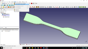
Click on ‘A’ under the drop-down box. Fig 7: A icon Selection
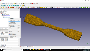
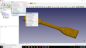
Select the top surface of the specimen and then click on the ‘Mesh’ tab to select ‘FEM Mesh by Gmsh’. Fig 8: Mesh Selection Window
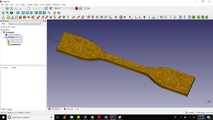
Enter the maximum element size as 1.0 and hit ‘Apply’ and ‘Ok’. The mesh might be hidden. To show the mesh, right click on the ‘FEMMeshGmsh’ in the model window and click on ‘Show Selection’. Fig 9: Mesh Selection WindowFig 10: Mesh Show Selection
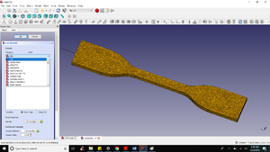
For adding the material, click on the ‘Model’ tab and click on ‘FEM Material for Solid’. Alternatively, you can click on the yellow circle right next to analysis button. You can select from the list of materials or give your own specifications for a material such as Young’s Modulus, Density and Poisson’s Ratio. For this tutorial, we select ABS. Press Ok. Fig 11: Material Icon SelectionFig 12: Material Drop down selection
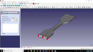
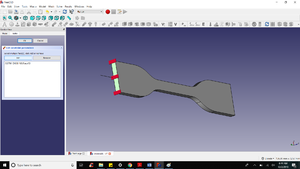
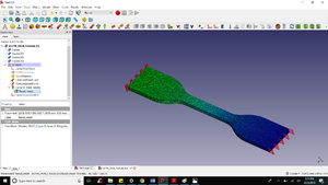
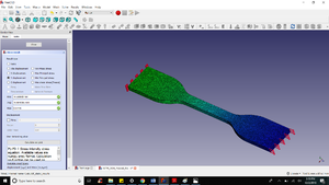
For adding constraints, click on the ‘Model’ tab and go to ‘Mechanical Constraints’ and then ‘Constraint fixed’. Select one of the flat face of specimen and click ‘Add’. Then click ‘Ok’ to exit. Fig 13: Material Constraint FixedFig 14: Constraint Face Selection
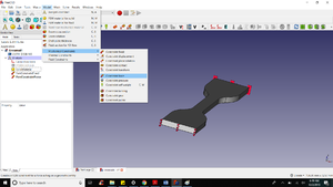
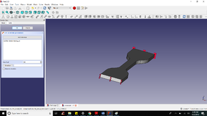
For Force constraint, again go to ‘Mechanical Constraints’ and click ‘Constraint force’. Select the other face of the specimen as shown. Enter the area load as 500 and press ‘Ok’.Fig 15: Mechanical Constraint Force SelectionFig 16: Mechanical Constraint Force Selection
Select ‘CalculiXccxTools’ in the model window. Now click on ‘Solve’ tab and hit ‘Run Solver Calculations’. Fig 17: Mesh Result
Double click on the ‘CalculiX_static_results’ and select the result you want on display. Fig 19: Displacement Result