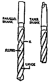
The twist drills used for drilling through metal are much the same as those used for woodwork. These drills range in size from .0135 inch upward. On larger drills it is customary to use high-speed steel, with a shank of tough steel butt-welded to it. Small drills (up to1/2 inch) are usually made with parallel shanks, while larger drills are more frequently designed with a tapered shank.
The tapered shank wedges itself in the spindle of the drilling machine, which has a corresponding tapered hole, and as more pressure is applied the drill becomes more firmly gripped. In addition, how- ever, the drill is made with a tongue or tang which fits into a corresponding slot in tho spindle of the drill press. This provides a more positive drive.
The drill body is the main portion that is used for the actual drilling and is made accurately to the specified size, although it is usually ground slightly less toward the shank end, so that there is a small clearance of not more than 1/1000 inch. The lands are the narrow strips along the cutting edge of the flutes. It is the diameter across these which is made accurately to size and which represents the size of the drill The portion of the body marked X in Fig. 1 is ground away slightly to prevent friction.
The flutes are made to ensure the correct cutting angle and at the same time give sufficient clearance for the waste material to flow out of the hole. This angle (Fig. 2) is called the angle of twist and is usually about 27 ½ degrees. The cutting angle is the degree of sharpness or bluntness of the drill and varies with the kind of material to be drilled. Standard drills are usually ground to a cutting angle of 59 degrees and this is most suited for general work. The surfaces formed by grinding the end of the drill to the cutting angle are then further ground so that the cutting edge slopes back at from 10 to 15 degrees; this angle is known as the clearance angle, and is also indicated in Fig. 2.
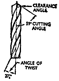
Notes on Drilling. Great care must he taken to ensure that the cutting angle and the clearance angle are maintained when a drill is reground; the angle of twist cannot, of course, be altered by grinding.
The following are a few of the faults that are likely to occur when drilling, owing to faulty grinding. If the hole is larger than the drill, it is probable that the two cutting angles are not identical. This would throw the drill point out of center and cause the drill to wobble. The result would be a hole larger than it should be. In addition, if the angles of both the cutting edges are not the same, one lip does all the work and dulls quickly. To correct this the drill must be reground.
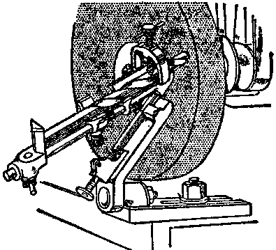
Special drill grinding appliances (see Fig. 3) that can be attached to power-driven grinding wheels make it possible to regrind a drill accurately and in short order. When drills are in need of grinding it is best to take them to a hardware store or metal shop having equipment of this type and have the drill ground there rather than try to do the work by hand. It is virtually impossible to get the correct angles by a hand process. The test for accurate regrinding is to place the drill in the hole it has made and see if it will drop vertically by its own weight through the hole. If it does not, it is clear that the hole is no larger than the drill that made it and the drill is therefore accurate. This is a very severe test.
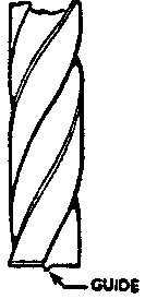
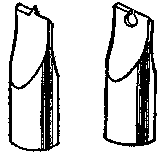
The angle of the drill tip is selected in relation to the hardness of the material on which it is to be used. A more acute angle can be used on soft metals than on very hard kinds. Thus, a 45 to 60 degree angle is a better cutting angle for cast iron than is the more general 59 degrees. An angle of 45 degrees is also more suitable for brass, although special drills may be obtained for brass which have their flutes straight, in addition to having the smaller cutting angle. Soft metals, such as copper or aluminum, are best cut with a drill having a cutting angle of 90 degrees and made with a small pip to act as a guide, as shown in Fig. 4.
Very hard steel, such as manganese steel, may be drilled more satisfactorily by using a drill having an angle of twist less than normal – say 24 degrees. The cutting angle should also be flatter – about 75 degrees.
Whenever a large hole has to be drilled, it is a good practice to drill a small hole first to act as a guide. This provides a center for the larger drill and reduces the risk of drilling a hole that is not exactly true.
Apart from the drills a1ready mentioned, there are specially designed drills for other kinds of work.
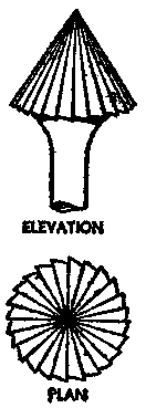
Fig. 5 shows a countersink bit like that used in woodworking. It is used to make holes for screw heads or rivets, and also for reaming. This type of countersink bitis intended mainly for use on soft metals. For normal countersinking a twist drill, twice the size of the hole that has been drilled, is used.
Fig. 6 shows a flat-ended drill by means of which a hole previously drilled to the correct depth with a twist drill may he squared out to a flat bottom; the small pip is necessary to ensure that the drill runs concentrically.
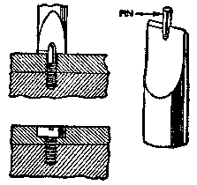
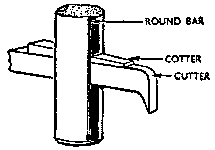
Fig. 7 shows another variety of the flat-ended drill that is used for recessing an existing hole to accommodate a bolt head or cheese-headed screw. The pin on the drill must be of the same diameter as the hole to be recessed. Large holes in thin metal are best cut by using a cutter and bar, the principle of which is shown in Fig. 8. A small hole is drilled first, and the center rod revolves in this; the cutter is then adjusted to the correct radius and the wedge-cotter tightened.
Drilling Machines. There is a wide variety of drilling machines, and these may be either power driven or hand operated.
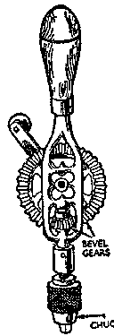
The small hand drill of the type shown in Fig. 9 is used chiefly for drilling small diameter holes in thin sheet metal, and is particularly useful for repair work and for drilling in positions where it is impossible to use a more powerful, larger machine. It is of the type used in carpentry: and about 12 inches in length; the three-jaw chuck will take drills up' to 1/4 inch in diameter. Care must be taken when using a hand drill keep it quite steady and in line with the twist drill. If this precaution is not observed, the resulting hole will be out of true and the drill will almost certainly be bent or broken.
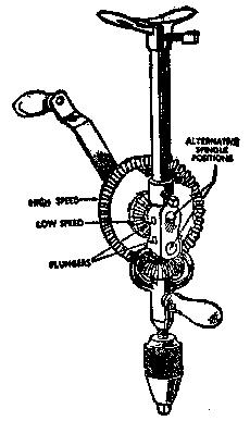
The breast drill shown in Fig. 10 is larger and more strongly made than the hand drill, and has an adjustable breastplate, by means of which a much greater pressure may be applied to the drill. The machine shown in Fig. 23 has two alternative speed ratios. These are obtained by moving the spindle of the driving wheel into one or another of the two positions as indicated in Fig. 23. In the first position the teeth around the outside of the large bevel wheel drive the small wheel attached to the chuck spindle; this gives a high speed drive. By moving the spindle, the inner set of teeth are engaged so that the chuck is rotated at a little more than the speed of the handle. It is only necessary to press a spring loaded plunger to allow the spindle to be withdrawn from either bushing. The three-jaw chuck on this type of machine generally has a capacity up to ½ inch. This drill is very well suited to the home workshop.
Power-Operated Drills. Until a few years ago, power-operated drills were bulky, heavy, and expensive machines found only in machine shops. Now, however, there ave many excellent brands of portable electric drills that are light in weight and are available to the horne mechanic at a reasonable cost. The smaller type of electric drills have a pistol grip and trigger switch so that the drill can be operated with one hand. By the use of special attachments these electric drills can be used for polishing, routing, and many other jobs, beside drilling metal. For very light metalwork there are electric hand tools which are considerably smaller and less expensive than the regulation electric power drills. These machines are very good for decorative metalwork as they can be purchased with attachments for engraving, routing, polishing, etc.
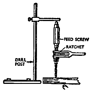
Other types of drilling equipment include the drill post and ratchet, which is a hand-operated tool used for drilling through thick or very hard metal. With this type of equipment the twist drill is made to revolve by means of a long handle and ratchet arrangement; it is fed slowly into the metal by means of a fine screw thread on the spindle and on the inside of the octagonal sleeve; The drill generally has a square tapered hole for square-shank drills instead of the three-jaw chuck (see Fig. 11).
Bench drills (Fig. 12), either power or hand operated, a stronger and more rigid than the other types of drills. They should be bolted to a bench.
Working the Drill. So far as the operation of a hand. drill is concerned, the only thing to be careful of is to keep the twist drill from being bent or broken by movement of the work or the drill itself. With power drills more care should be exercised, particularly in power- operated bench drills where, unless the machine is operated properly, there is danger of serious injury to the worker. The first rule in using a power-operated drill is to be sure that the drill is secure in the drill chuck and the work that is to be drilled is clamped in such a way that it will not be necessary to hold it with the hands. Another point is to use only a sharp drill. The correct speed to run the drill is very important in operating an electric drill. If a drill revolves too fast it becomes overheated, the correct temper is lost, and the drill becomes soft and hence useless. On the other hand, if insufficient pressure is used to make the drill cut the metal, the drill will be damaged. The larger the drill the more slowly it must revolve. The other factor that enters into the speed at which the drill can be operated is the hardness of the metal being drilled. With soft metals, such as copper and aluminum, the drill can be operated very fast, while with cast iron and steel the speed must be reduced considerably. The drill must be well lubricated during use, and while it is sufficient to apply the oilcan freely to hand or breast drills, this method is not satisfactory with larger power- driven drilling machines. For these a mixture of soap and water, or a mixture of soft soap, soda, and water, is used freely; this allows the drills to be run at increase speeds and feeds and at the same time prolongs the life of the drill by preventing overheating.
When the drill is just protruding through the metal that is being drilled, care is needed to prevent the drill from being pulled quickly into the partly cut hole and thus being broken. After some experience the operator can feel when this is about to happen, and he reduces the feed. Even so, considerably more effort is required to keep the work stationary and prevent it from revolving with the drill. It is wise to place a block of wood or soft metal under the work to prevent the drill from grabbing when it breaks through.
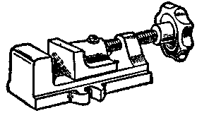
A small vise, such as shown in Fig. 13, should be used with bench drills to keep the work stationary. The vise is bolted to the base of the drill.
It frequently happens that a drill is broken – generally owing to careless use or bad grinding – and the body is left securely wedged into the partially drilled hole. It is then often very difficult to withdraw the broken portion. If any part of the drill projects, the ends may be gripped with pliers and the broken end withdrawn; unfortunately, the drill is so brittle that these small bits frequently crumble away before any real grip can be obtained. If it is at all feasible, the job should be heated to redness and allowed to cool as slowly as possible – say by burying it in cinders. The drill is then tough and soft, and the projecting portions can be used to pull out the broken parts.
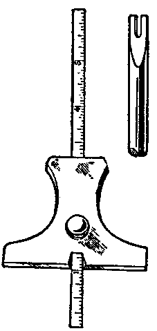
Where there is no projecting portion a small tool (Fig. 14) can be made or purchased. The two small fingers fit into the flutes of the broken drill, and it is possible to revolve the drill in the hole and so unscrew it. Failing these methods, the drill must be softened as described and drilled out with a new drill.