Sophivorus (talk | contribs) m (Rename "affiliations" parameter to "organizations", to unify terminology throughout Appropedia) |
|||
| (367 intermediate revisions by 12 users not shown) | |||
| Line 1: | Line 1: | ||
{{Solar menu}} | |||
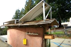
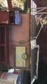
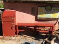
[[File:CCAT kiosk 1.JPG|thumb]] | |||
{{Project data | |||
| authors = User:Ths79, User:TyMuho | |||
| status = Deployed | |||
| completed = 2017 | |||
| cost = USD 156.28 | |||
| instance-of = Photovoltaic system | |||
| location = Arcata, California | |||
}} | |||
The '''solar kiosk''' is a charging station that has a "Dual USB Power Charger" that has its own volt regulator inside and a volt regulator to control the volts coming out from the panels at about 24V max and in to an inverter at 12 volts direct current (DC). The inverter is 200 watts which supports two 120V alternative current (AC) and has a USB port. There is also a 20 Amp fuse on the positive wire coming from the panels that will stop the flow of electricity if there is too high of a current flowing through. | |||
The | |||
[[ | This project was implemented because [[CCAT]] had two 100 watt solar panels that served no purpose, but were already mounted on a wall in an optimal location for sunlight. Solar panels are designed to absorb the sun's light and convert it to electricity for our consumption. | ||
CCAT wanted a simple yet fun way for people to directly see where their energy is coming from. The system consists of no [[Deep-cycle lead-acid batteries for renewable energy storage|lead acid battery]], so the system can only run if there is enough sun to generate enough current and voltage. With no battery, we are [[How to reduce your carbon footprint|reducing our carbon impact]] as well as showing the educational purpose of the system to the full extent; it only works with sufficient sunlight. This demonstrates what it is like to use energy off the grid that is a renewable energy source which decreases your carbon footprint as well. | |||
== Background == | |||
At Cal Poly Humboldt in Arcata, California, the Campus Center for Appropriate Technology ([[CCAT]]) has a pair of [[photovoltaics]] solar panels that are currently not in use. They were originally from a past project called [[CCAT Solar Charging Station]] which was created as a solar charging station for students to charge electronics while outside. There is a battery, charge controller box, a USB converter, and fuse cords along with the solar panels, but are not in working condition and will need to be replaced in order for the solar panels to function properly. The panels are 100 watts each and in good condition. For the course, [[Engr305 Appropriate Technology]] this spring of 2017, students [[User:TyMuho|Ty M.]] and [[User:Ths79|Tyler S.]] have been given the task to make use of the solar panels into a "Solar Kiosk" stand where students will be able to learn the potential of [[off-the-grid]] solar use as well as enjoy possible music box and phone charging capabilities. This will demonstrate the use of appropriate technology, turning something old into a new, updated more appropriate use of the solar panels for CCAT's needs. They would like to see a functioning solar kiosk come to life. The kiosk will be located near the [[CCAT papercrete clayslip demo wall]] in front of the house. The project will be implemented in the late spring semester of 2017. | |||
<center> | |||
<gallery> | |||
File:Kiosk at use.JPG|Solar kiosk at use | |||
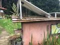
File:CCAT solar kiosk.JPG|CCAT Solar Kiosk area | |||
File:Inside look of the kiosk.JPG|Inside Look of the Kiosk | |||
File:ENGR305 cartoon diagram.jpg| Cartoon Diagram of System | |||
File:CCAT Solar Kiosk Side Angle.jpeg|Front of CCAT solar kiosk | |||
File:CCAT solar kiosk; back.JPG|Back of CCAT solar kiosk | |||
File:CCAT solar kiosk; charge controller.JPG|Current charge controller | |||
</gallery></center> | |||
== Problem statement and criteria == | |||
The objective of this project is to reactivate CCAT's two functional solar panels so that they will provide renewable energy to the public and satisfy a small portion of the population energy demands. This project will look into finding the best application of power for the kiosk given possible limitations. | |||
The following criteria will be used to address the Solar Kiosk's success. These criteria were chosen based on the recommendations of one of the [[CCAT]] directors as well as the students working on this project, [[User:Ths79|Tyler S.]] and [[User:TyMuho|Ty M.]] The following criteria and constraints are ranked from 1-10, indicating how crucial they are to the project with 10 being the top priority. | |||
{| class="wikitable" | |||
! Criteria | |||
! Constraints | |||
! Weight<br>(1-10) | |||
|- | |||
| Reusable Material | |||
| Parts from the previous [[CCAT Solar Charging Station|Solar Kiosk project]] may be used again as well as local used materials. | |||
| 6 | |||
|- | |||
| [[Direct current|DC]] Appliances | |||
| Only certain electronic devices under a specific amount of wattage may be used. | |||
| 8 | |||
|- | |||
| Functionality | |||
| Transfers solar energy into usable electricity. | |||
| 10 | |||
|- | |||
| Energy Usage | |||
| Try to not buy new materials or else it defeats the purpose of self sustaining energy. | |||
| 9 | |||
|- | |||
| Accessibility | |||
| Available/easy access to the public for charging an electronic device. | |||
| 8 | |||
|- | |||
| Educational | |||
| Informs the public about the potential of solar energy and demonstrates an example system. | |||
| 9 | |||
|- | |||
| Cost | |||
| Must not exceed budget | |||
| 8 | |||
|- | |||
| Legibility, Readability, and Comprehension | |||
| Make sure the project is understandable for the general public. | |||
| 9 | |||
|- | |||
| Aesthetics | |||
| Professional and interesting to make people want to use it/check it out. | |||
| 7 | |||
|} | |||
== Literature review and references == | |||
To see the full literature review and references section for this project click [[CCAT solar kiosk/Literature review|here]] | |||
== Construction == | |||
[[File:ENGR305 wiring schematic.jpg|thumb|center|600px|Wiring Schematic]] | |||
=== Solar kiosk === | |||
<gallery | |||
File: | All of the wood that was used for the solar kiosk was use provided by CCAT. | ||
File: | |||
File: | # Make a cube without the front on it with the following dimensions; Depth = 20 inches, Width = 17.25 inches and Height =23.25 inches. | ||
# Make a second cube without the front on it then place and screw on top of the first cube with the following dimensions; Depth = 20 inches, Width = 18.25 inches and Height 6 inches. | |||
# Create two doors (one for bottom cube and one for top cube) and attach hinges and locks for each door. The dimensions for the bottom door is; Depth =.5 inches, Width 16.25 inches and Height 22.25 inches. The dimensions for the top door is; Depth =.5 inches, Width 15.25 inches and Height 5 inches. | |||
# For staining purposes, we used Redwood Stain Latex which we bought at Ace Hardware. We used brushes and started staining with the grain of the wood. We applied two coats of stain. | |||
<gallery> | |||
File:IMG 0585.JPG | Solar Kiosk Prototype | |||
File:IMG 0609.JPG | Partial Stain | |||
File:IMG 0615.JPG | Finished Staining | |||
</gallery> | </gallery> | ||
=== | === Bench === | ||
[[File:IMG 0613.JPG|thumb|Staining Bench]] | |||
== | The volume of the bench would take up is; Depth = 12 inches, Width = 30 inches and Height is 16 inches. | ||
# On top of the bench there are 4 boards that are 2 inches high and 6 inches wide with a depth of 15 inches. | |||
# The height of all the legs is roughly 14 inches, with a width and length of 2 by 4 inches. | |||
# The 4 reinforcing beams perpendicular to the legs are roughly 2 inches wide by 4 inches high with a depth of 6 inches. | |||
# The 2 reinforcing beams connected to the 4 reinforcing beams are roughly 2 inches high and 6 inches wide with a depth of 13 | |||
# The final board adds reinforcement to where people sit on top of the bench with a width of 6 inches a height of 2 inches and a depth of 15 inches. | |||
=== Wiring === | |||
The wiring construction of this project went as followed: | |||
# Locate the positive and negative end of the cord coming out of the solar panels and locate the positive and negative wires coming out of the input on the volt regulator. | |||
# Wire a fuse in between the two positive terminals, one from the panels and one from the volt regulator. | |||
# After the two positive terminals are wired, connect the negative (Solar panel) terminal to the negative terminal of the Volt Regulator under where it says input. | |||
# Where is says output on the Volt Regulator, wire the positive (Volt Regulator) terminal to the positive (USB device) terminal and the negative (Volt Regulator) terminal to the negative (USB device) terminal. | |||
# Wire the positive (USB device) terminal to the positive (Inverter) terminal and the negative (USB device) terminal to the negative (Inverter) terminal. | |||
# Once your done wiring, test the inverter to make sure it works. If it works, solder the wires together in the same order as steps 1-5 describe. | |||
== Timeline == | |||
=== Proposed timeline === | |||
{| class="wikitable" | {| class="wikitable" | ||
! Objectives | |||
! Start date | |||
! Completion date | |||
|- | |||
| Prototype photos/draw-ups | |||
| 2/14/2017 | |||
| 2/19/2017 | |||
|- | |||
| Collect Reusable Material | |||
| 2/16/2017 | |||
| 2/26/2017 | |||
|- | |- | ||
| Purchase Project Components | |||
| 2/20/2017 | |||
| 3/1/2017 | |||
|- | |- | ||
| | | Collect Testable [[Direct current|DC]] Appliances | ||
| | | 2/20/2017 | ||
| | | 3/2/2017 | ||
|- | |- | ||
| | | Project Design | ||
| | | 2/27/2017 | ||
| | | 3/7/2017 | ||
|- | |||
| Implementation of Solar System | |||
| 3/9/2017 | |||
| 5/1/2017 | |||
|- | |||
| Create Interpretative Signage | |||
| 4/21/2017 | |||
| 5/5/2017 | |||
|- | |||
| Test Project | |||
| 5/2/2017 | |||
| 5/12/2017 | |||
|} | |} | ||
=== Actual timeline === | |||
{| class="wikitable" | |||
! Objectives | |||
! Start date | |||
! Completion date | |||
|- | |||
| Prototype photos/draw-ups | |||
| 2/14/2017 | |||
| 2/19/2017 | |||
|- | |||
| Build Solar Kiosk Framework | |||
| 3/5/2017 | |||
| 4/2/2017 | |||
|- | |||
| Draw wiring schematic and receive CCAT's approval | |||
| 4/5/2017 | |||
| 4/5/2017 | |||
|- | |||
| Build Bench | |||
| 4/8/2017 | |||
| 4/15/2017 | |||
|- | |||
| Stain | |||
| 4/23/2017 | |||
| 4/28/2017 | |||
|- | |||
| Purchase Inverter, fuse and holder, and Volt Regulator | |||
| 4/292017 | |||
| 4/29/2017 | |||
|- | |||
| Implement Wiring System | |||
| 5/6/2017 | |||
| 5/6/2017 | |||
|- | |||
| Test Project | |||
| 5/8/2017 | |||
| 5/8/2017 | |||
|} | |||
== Cost == | |||
The following shows the materials used in our project as well as where they came from and price. [[CCAT]] has already donated two solar panels and wood, the rest of the technology will be bought from online or local stores. Material for the creation of the solar kiosk will be used and reclaimed material from various local shops and online. | |||
{| class="wikitable" | |||
! Quantity | |||
! Material | |||
! Source | |||
! Cost ($) | |||
|- | |||
| 1 | |||
| Sandpaper 4.5x11F 5PK and Sandpaper 4x4.5 CRS 60Grit | |||
| Ace Hardware | |||
| $8.12 | |||
|- | |||
| 1 | |||
| In-Line Fush Holder AGC | |||
| Ace Hardware | |||
| $4.87 | |||
|- | |||
| 1 | |||
| 158PC Wire Connector ASST and AGC Glass Auto Fuse 60PC | |||
| Harbor Freight Tools | |||
| $12.99 | |||
|- | |||
| 3 | |||
| Stain Latex Redwood Quart | |||
| Ace Hardware | |||
| $19.08 | |||
|- | |||
| 1 | |||
| Screw WD PH CS6X1-5/8 and Hinge Narrow2-1/2 BB CD2 | |||
| Ace Hardware | |||
| $13.00 | |||
|- | |||
| 2 | |||
| Barrel Bolt 4 inches | |||
| Ace Hardware | |||
| $13.98 | |||
|- | |||
| 1 | |||
| Pull Utility 6-1/2 inches and Sash Lift and Hinge Narrow 2 | |||
| Ace Hardware | |||
| $16.57 | |||
|- | |||
| 2 | |||
| 100 Watt Solar Panels | |||
| CCAT | |||
| $0.00 | |||
|- | |||
| 1 | |||
| 200W/400W Power Inverter | |||
| Harbor Freight Tools | |||
| $21.69 | |||
|- | |||
| 1 | |||
| 24V Volt Regulator | |||
| Amazon | |||
| $19.98 | |||
|- | |||
| 34 | |||
| All pieces of wood and screws were provided by CCAT | |||
| CCAT | |||
| $0.00 | |||
|- | |||
| 1 | |||
| 127 PC HS Tubing ASST W/CA and Soldering Iron Gun with Stan | |||
| Harbor Freight Tools | |||
| $9.00 | |||
|- | |||
| 1 | |||
| Informational Panel | |||
| Fedex | |||
| $17.00 | |||
|- | |||
! colspan="3" | Total Cost | |||
! $156.28 | |||
|} | |||
== Operation and maintenance == | |||
=== Operation === | |||
As this system has no [[Deep-cycle lead-acid batteries for renewable energy storage|lead acid battery]], it has to be sunny out in order for the solar kiosk to work. That being said these are the operation instructions: | |||
# Arrive in front of CCAT and go towards the two solar panels on top of the [[CCAT papercrete clayslip demo wall]] | |||
# You will see a bench and kiosk charging station | |||
# Open the smallest cabinet on the top | |||
# Turn on the inverter | |||
# Plug in a three prong AC device or connect to the USB outlets | |||
# Turn OFF the inverter before you leave and close drawer | |||
=== Maintenance === | |||
The following parts will be checked for this project: | |||
* Does the inverter turn on, a green light should appear, and charges a device | |||
* Check for water log inside the drawers of the kiosk. This may mean there is a leak somewhere | |||
* Make sure informative sign is visible/clean | |||
* Clean off the surface of solar panels | |||
* Check the bottom of the kiosk and the bench legs to see how it is holding up | |||
=== Schedule === | |||
Every two weeks check: | |||
* Especially before it starts raining, make sure wires running down from panels to the kiosk are making a "U" shape in order to prevent water from dripping into the inverter | |||
* If the inverter turns on and charges a device | |||
* For water log inside the drawers of the kiosk | |||
* To make sure informative sign is visible/clean | |||
Every month: | |||
* Clean off the surface of solar panels | |||
* Check the bottom of the kiosk and the bench legs to see how it is holding up | |||
== Discussion == | == Discussion == | ||
=== Conclusion === | |||
The solar panels that were provided to us by CCAT allow us to convert sunlight into electricity by using the following items; solar panels, fuse, volt regulator and an inverter. However not any AC appliance will function while plugged into the inverter, it has to be 200 watts or less when plugged into the inverter. Some devices that we used on our inverter were an iPhone charger and a laptop charging cord. With the right materials it is relatively simple to design your own solar system and you will be able to generate electricity in a very short time. | |||
NOTE: We have left two 20 Amp fuses taped to the top of the top drawer when needed. | |||
=== Lessons learned === | |||
Some lessons that I learned while creating this solar system include the following: | |||
* One can not be careless when designing an electric system. For example, if the output of a solar system is 24 volts, the inverter has to be under 24 volts in order for it to work. Or getting the right sized volt regulator, which should be higher than what the solar panels are outputting, to maintain a constant voltage that gets delivered to the inverter. Building the wooden bench and kiosk should be the least amount of our effort, even though it actually took longer to cut and build. Determining the size of a screw or a piece of a board does not matter in the end. In the end, making sure the electrical part is sized right is most important. | |||
* Weather can be difficult to work with when designing a solar power system, because the electrical system relies on the sun to produce energy, we cannot test to see if the system works unless the sun is out. Also, one can not build an electrical system while it is raining. | |||
* Everything will not go according to plan, so start working on a project earlier than later. In addition if there are problems, one can fix them and still be on track. | |||
=== Next steps === | === Next steps === | ||
The next steps. | The most important next steps would be to get the wiring completely soldered. Right now the inverter is not soldered and only connected with alligator clips. This also makes the system open to theft so the inverter should be soldered on both sides of connection. Also, if after people start using the system and find they wish the USB dual charger port was more extendable, the wires will need to be replaced with wires for lamps or something of the sort. Also, maintenance check ups and using the system to know first hand if it's still charging. Other then that we will most likely not expand this project any further. Next steps could be to find what the biggest thing the panels could power, and do analysis testing on the system. | ||
Some other important things to do is make the inside of the top drawer, where all the equipment is, more waterproof. This can be done by putting pond liner around the inside of the top drawer. We have left some extra liner in the bottom cabinet. Also, the whole in the back of the box where the wires run into should be sealed up as well with a type of epoxy. | |||
== Testing results == | |||
After Ty and I connected all the wires together on May 6 (see wiring section under construction) we turned on the inverter and were able to power the following devices with their appropriate cords. First was an iphone and second was an apple laptop. The wattage on both devices were under 200 and that number is the max amount of watts the system can produce. | |||
We found the efficiency of the panels to be 11.1% by using the formula =(Panel Power output)/((1000watt/m^2)(Area of panel)). We connected 200 watts to the inverter and covered one of the panels at 11 a.m. completely causing the inverter light to go red, which means the panels were not able to supply enough power to the inverter. We slowly uncovered the covered solar panel and at about half way uncovered, the inverter light turned green and supplied power once again. | |||
== Troubleshooting == | |||
* '''Sun not available''' — The availability of the sun depends on the weather thus we can not solve this problem. | |||
* '''Wire damage''' — The wire can be easily cut with the right equipment, therefore new wiring would need to be purchased. | |||
* '''Stolen parts''' — To solve this problem we will screw in the following devices, first screw in a tupperware into the bottom on the top cabinet where the inverter sits in. If this is a major issue, the simple hinge lock on the drawer could be changed to have a lock on it that CCAT could lock at night. Second the solar panels are screwed into the clay slip wall structure. Third the solar kiosk is really heavy to lift so it would be difficult to steal, same as with the bench. And forth, the wires are screwed into the inverter, are fused with the volt regulator and fused with the wires coming from the solar panels. | |||
* '''Broken parts''' — If the inverter, wires, volt regulator or the solar panels do not work. We would have to take it apart and use a multi-meter to determine where the voltage is not present. | |||
== Update September 2018 == | |||
[[File:UpdatedSolarKiosk.jpg|thumb|Update September 2018]] | |||
The inverter for the solar kiosk has been stolen. The wooden frame of the kiosk is being repurposed to serve as a weighing station for the food production from the gardens. The kiosk allows for food data collection capabilities and has a garden map. The solar charging station will be functional again when a new inverter is put into place. | |||
== Related projects == | |||
= | {{Gallery | ||
| instance-of = Photovoltaic system | |||
}} | |||
== See also == | |||
* [[Commercially available photovoltaic modules]] | |||
* [[Solar photovoltaic ground mounting]] | |||
* [[Solar Photovoltaic Cells for the Kingston Home FAQ|Solar Photovoltaic Cells FAQ]] | |||
* [[Maintenance of your Solar Electric System]] | |||
{{Page data | |||
| part-of = Engr305 Appropriate Technology | |||
| keywords = ccat, charging station, kiosk, photovoltaic, solar, power inverter, solar panels, wood, solar kiosk, CCAT | |||
| sdg = SDG07 Affordable and clean energy, SDG11 Sustainable cities and communities | |||
| published = 2017 | |||
| organizations = Campus Center for Appropriate Technology (CCAT), Cal Poly Humboldt Students | |||
| license = CC-BY-SA-3.0 | |||
| language = en | |||
}} | |||
[[Category:Wood]] | |||
[[Category:CCAT]] | |||
[[Category: | |||
Latest revision as of 16:09, 29 January 2024

The solar kiosk is a charging station that has a "Dual USB Power Charger" that has its own volt regulator inside and a volt regulator to control the volts coming out from the panels at about 24V max and in to an inverter at 12 volts direct current (DC). The inverter is 200 watts which supports two 120V alternative current (AC) and has a USB port. There is also a 20 Amp fuse on the positive wire coming from the panels that will stop the flow of electricity if there is too high of a current flowing through.
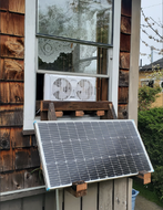
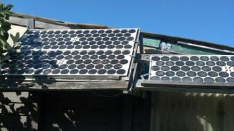
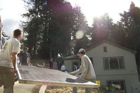
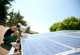
This project was implemented because CCAT had two 100 watt solar panels that served no purpose, but were already mounted on a wall in an optimal location for sunlight. Solar panels are designed to absorb the sun's light and convert it to electricity for our consumption.
CCAT wanted a simple yet fun way for people to directly see where their energy is coming from. The system consists of no lead acid battery, so the system can only run if there is enough sun to generate enough current and voltage. With no battery, we are reducing our carbon impact as well as showing the educational purpose of the system to the full extent; it only works with sufficient sunlight. This demonstrates what it is like to use energy off the grid that is a renewable energy source which decreases your carbon footprint as well.
Background[edit | edit source]
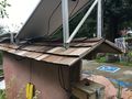
At Cal Poly Humboldt in Arcata, California, the Campus Center for Appropriate Technology (CCAT) has a pair of photovoltaics solar panels that are currently not in use. They were originally from a past project called CCAT Solar Charging Station which was created as a solar charging station for students to charge electronics while outside. There is a battery, charge controller box, a USB converter, and fuse cords along with the solar panels, but are not in working condition and will need to be replaced in order for the solar panels to function properly. The panels are 100 watts each and in good condition. For the course, Engr305 Appropriate Technology this spring of 2017, students Ty M. and Tyler S. have been given the task to make use of the solar panels into a "Solar Kiosk" stand where students will be able to learn the potential of off-the-grid solar use as well as enjoy possible music box and phone charging capabilities. This will demonstrate the use of appropriate technology, turning something old into a new, updated more appropriate use of the solar panels for CCAT's needs. They would like to see a functioning solar kiosk come to life. The kiosk will be located near the CCAT papercrete clayslip demo wall in front of the house. The project will be implemented in the late spring semester of 2017.
-
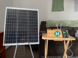
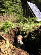
Solar kiosk at use
-
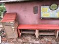
CCAT Solar Kiosk area
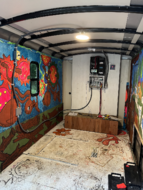
-
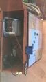
Inside Look of the Kiosk
-
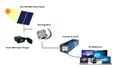
Cartoon Diagram of System
-
Front of CCAT solar kiosk
-
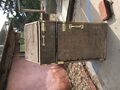
Back of CCAT solar kiosk
-
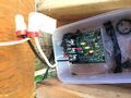
Current charge controller


Problem statement and criteria[edit | edit source]
The objective of this project is to reactivate CCAT's two functional solar panels so that they will provide renewable energy to the public and satisfy a small portion of the population energy demands. This project will look into finding the best application of power for the kiosk given possible limitations.
The following criteria will be used to address the Solar Kiosk's success. These criteria were chosen based on the recommendations of one of the CCAT directors as well as the students working on this project, Tyler S. and Ty M. The following criteria and constraints are ranked from 1-10, indicating how crucial they are to the project with 10 being the top priority.
| Criteria | Constraints | Weight (1-10) |
|---|---|---|
| Reusable Material | Parts from the previous Solar Kiosk project may be used again as well as local used materials. | 6 |
| DC Appliances | Only certain electronic devices under a specific amount of wattage may be used. | 8 |
| Functionality | Transfers solar energy into usable electricity. | 10 |
| Energy Usage | Try to not buy new materials or else it defeats the purpose of self sustaining energy. | 9 |
| Accessibility | Available/easy access to the public for charging an electronic device. | 8 |
| Educational | Informs the public about the potential of solar energy and demonstrates an example system. | 9 |
| Cost | Must not exceed budget | 8 |
| Legibility, Readability, and Comprehension | Make sure the project is understandable for the general public. | 9 |
| Aesthetics | Professional and interesting to make people want to use it/check it out. | 7 |
Literature review and references[edit | edit source]
To see the full literature review and references section for this project click here
Construction[edit | edit source]

Solar kiosk[edit | edit source]
All of the wood that was used for the solar kiosk was use provided by CCAT.
- Make a cube without the front on it with the following dimensions; Depth = 20 inches, Width = 17.25 inches and Height =23.25 inches.
- Make a second cube without the front on it then place and screw on top of the first cube with the following dimensions; Depth = 20 inches, Width = 18.25 inches and Height 6 inches.
- Create two doors (one for bottom cube and one for top cube) and attach hinges and locks for each door. The dimensions for the bottom door is; Depth =.5 inches, Width 16.25 inches and Height 22.25 inches. The dimensions for the top door is; Depth =.5 inches, Width 15.25 inches and Height 5 inches.
- For staining purposes, we used Redwood Stain Latex which we bought at Ace Hardware. We used brushes and started staining with the grain of the wood. We applied two coats of stain.
-
Solar Kiosk Prototype
-
Partial Stain
-
Finished Staining


Bench[edit | edit source]

The volume of the bench would take up is; Depth = 12 inches, Width = 30 inches and Height is 16 inches.
- On top of the bench there are 4 boards that are 2 inches high and 6 inches wide with a depth of 15 inches.
- The height of all the legs is roughly 14 inches, with a width and length of 2 by 4 inches.
- The 4 reinforcing beams perpendicular to the legs are roughly 2 inches wide by 4 inches high with a depth of 6 inches.
- The 2 reinforcing beams connected to the 4 reinforcing beams are roughly 2 inches high and 6 inches wide with a depth of 13
- The final board adds reinforcement to where people sit on top of the bench with a width of 6 inches a height of 2 inches and a depth of 15 inches.
Wiring[edit | edit source]
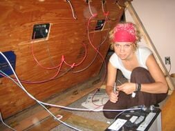
The wiring construction of this project went as followed:
- Locate the positive and negative end of the cord coming out of the solar panels and locate the positive and negative wires coming out of the input on the volt regulator.
- Wire a fuse in between the two positive terminals, one from the panels and one from the volt regulator.
- After the two positive terminals are wired, connect the negative (Solar panel) terminal to the negative terminal of the Volt Regulator under where it says input.
- Where is says output on the Volt Regulator, wire the positive (Volt Regulator) terminal to the positive (USB device) terminal and the negative (Volt Regulator) terminal to the negative (USB device) terminal.
- Wire the positive (USB device) terminal to the positive (Inverter) terminal and the negative (USB device) terminal to the negative (Inverter) terminal.
- Once your done wiring, test the inverter to make sure it works. If it works, solder the wires together in the same order as steps 1-5 describe.
Timeline[edit | edit source]
Proposed timeline[edit | edit source]
| Objectives | Start date | Completion date |
|---|---|---|
| Prototype photos/draw-ups | 2/14/2017 | 2/19/2017 |
| Collect Reusable Material | 2/16/2017 | 2/26/2017 |
| Purchase Project Components | 2/20/2017 | 3/1/2017 |
| Collect Testable DC Appliances | 2/20/2017 | 3/2/2017 |
| Project Design | 2/27/2017 | 3/7/2017 |
| Implementation of Solar System | 3/9/2017 | 5/1/2017 |
| Create Interpretative Signage | 4/21/2017 | 5/5/2017 |
| Test Project | 5/2/2017 | 5/12/2017 |
Actual timeline[edit | edit source]
| Objectives | Start date | Completion date |
|---|---|---|
| Prototype photos/draw-ups | 2/14/2017 | 2/19/2017 |
| Build Solar Kiosk Framework | 3/5/2017 | 4/2/2017 |
| Draw wiring schematic and receive CCAT's approval | 4/5/2017 | 4/5/2017 |
| Build Bench | 4/8/2017 | 4/15/2017 |
| Stain | 4/23/2017 | 4/28/2017 |
| Purchase Inverter, fuse and holder, and Volt Regulator | 4/292017 | 4/29/2017 |
| Implement Wiring System | 5/6/2017 | 5/6/2017 |
| Test Project | 5/8/2017 | 5/8/2017 |
Cost[edit | edit source]
The following shows the materials used in our project as well as where they came from and price. CCAT has already donated two solar panels and wood, the rest of the technology will be bought from online or local stores. Material for the creation of the solar kiosk will be used and reclaimed material from various local shops and online.
| Quantity | Material | Source | Cost ($) |
|---|---|---|---|
| 1 | Sandpaper 4.5x11F 5PK and Sandpaper 4x4.5 CRS 60Grit | Ace Hardware | $8.12 |
| 1 | In-Line Fush Holder AGC | Ace Hardware | $4.87 |
| 1 | 158PC Wire Connector ASST and AGC Glass Auto Fuse 60PC | Harbor Freight Tools | $12.99 |
| 3 | Stain Latex Redwood Quart | Ace Hardware | $19.08 |
| 1 | Screw WD PH CS6X1-5/8 and Hinge Narrow2-1/2 BB CD2 | Ace Hardware | $13.00 |
| 2 | Barrel Bolt 4 inches | Ace Hardware | $13.98 |
| 1 | Pull Utility 6-1/2 inches and Sash Lift and Hinge Narrow 2 | Ace Hardware | $16.57 |
| 2 | 100 Watt Solar Panels | CCAT | $0.00 |
| 1 | 200W/400W Power Inverter | Harbor Freight Tools | $21.69 |
| 1 | 24V Volt Regulator | Amazon | $19.98 |
| 34 | All pieces of wood and screws were provided by CCAT | CCAT | $0.00 |
| 1 | 127 PC HS Tubing ASST W/CA and Soldering Iron Gun with Stan | Harbor Freight Tools | $9.00 |
| 1 | Informational Panel | Fedex | $17.00 |
| Total Cost | $156.28 | ||
Operation and maintenance[edit | edit source]
Operation[edit | edit source]
As this system has no lead acid battery, it has to be sunny out in order for the solar kiosk to work. That being said these are the operation instructions:
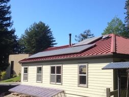
- Arrive in front of CCAT and go towards the two solar panels on top of the CCAT papercrete clayslip demo wall
- You will see a bench and kiosk charging station
- Open the smallest cabinet on the top
- Turn on the inverter
- Plug in a three prong AC device or connect to the USB outlets
- Turn OFF the inverter before you leave and close drawer
Maintenance[edit | edit source]
The following parts will be checked for this project:
- Does the inverter turn on, a green light should appear, and charges a device
- Check for water log inside the drawers of the kiosk. This may mean there is a leak somewhere
- Make sure informative sign is visible/clean
- Clean off the surface of solar panels
- Check the bottom of the kiosk and the bench legs to see how it is holding up
Schedule[edit | edit source]
Every two weeks check:
- Especially before it starts raining, make sure wires running down from panels to the kiosk are making a "U" shape in order to prevent water from dripping into the inverter
- If the inverter turns on and charges a device
- For water log inside the drawers of the kiosk
- To make sure informative sign is visible/clean
Every month:
- Clean off the surface of solar panels
- Check the bottom of the kiosk and the bench legs to see how it is holding up
Discussion[edit | edit source]
Conclusion[edit | edit source]
The solar panels that were provided to us by CCAT allow us to convert sunlight into electricity by using the following items; solar panels, fuse, volt regulator and an inverter. However not any AC appliance will function while plugged into the inverter, it has to be 200 watts or less when plugged into the inverter. Some devices that we used on our inverter were an iPhone charger and a laptop charging cord. With the right materials it is relatively simple to design your own solar system and you will be able to generate electricity in a very short time.
NOTE: We have left two 20 Amp fuses taped to the top of the top drawer when needed.
Lessons learned[edit | edit source]
Some lessons that I learned while creating this solar system include the following:
- One can not be careless when designing an electric system. For example, if the output of a solar system is 24 volts, the inverter has to be under 24 volts in order for it to work. Or getting the right sized volt regulator, which should be higher than what the solar panels are outputting, to maintain a constant voltage that gets delivered to the inverter. Building the wooden bench and kiosk should be the least amount of our effort, even though it actually took longer to cut and build. Determining the size of a screw or a piece of a board does not matter in the end. In the end, making sure the electrical part is sized right is most important.
- Weather can be difficult to work with when designing a solar power system, because the electrical system relies on the sun to produce energy, we cannot test to see if the system works unless the sun is out. Also, one can not build an electrical system while it is raining.
- Everything will not go according to plan, so start working on a project earlier than later. In addition if there are problems, one can fix them and still be on track.
Next steps[edit | edit source]
The most important next steps would be to get the wiring completely soldered. Right now the inverter is not soldered and only connected with alligator clips. This also makes the system open to theft so the inverter should be soldered on both sides of connection. Also, if after people start using the system and find they wish the USB dual charger port was more extendable, the wires will need to be replaced with wires for lamps or something of the sort. Also, maintenance check ups and using the system to know first hand if it's still charging. Other then that we will most likely not expand this project any further. Next steps could be to find what the biggest thing the panels could power, and do analysis testing on the system.
Some other important things to do is make the inside of the top drawer, where all the equipment is, more waterproof. This can be done by putting pond liner around the inside of the top drawer. We have left some extra liner in the bottom cabinet. Also, the whole in the back of the box where the wires run into should be sealed up as well with a type of epoxy.
Testing results[edit | edit source]
After Ty and I connected all the wires together on May 6 (see wiring section under construction) we turned on the inverter and were able to power the following devices with their appropriate cords. First was an iphone and second was an apple laptop. The wattage on both devices were under 200 and that number is the max amount of watts the system can produce.
We found the efficiency of the panels to be 11.1% by using the formula =(Panel Power output)/((1000watt/m^2)(Area of panel)). We connected 200 watts to the inverter and covered one of the panels at 11 a.m. completely causing the inverter light to go red, which means the panels were not able to supply enough power to the inverter. We slowly uncovered the covered solar panel and at about half way uncovered, the inverter light turned green and supplied power once again.
Troubleshooting[edit | edit source]
- Sun not available — The availability of the sun depends on the weather thus we can not solve this problem.
- Wire damage — The wire can be easily cut with the right equipment, therefore new wiring would need to be purchased.
- Stolen parts — To solve this problem we will screw in the following devices, first screw in a tupperware into the bottom on the top cabinet where the inverter sits in. If this is a major issue, the simple hinge lock on the drawer could be changed to have a lock on it that CCAT could lock at night. Second the solar panels are screwed into the clay slip wall structure. Third the solar kiosk is really heavy to lift so it would be difficult to steal, same as with the bench. And forth, the wires are screwed into the inverter, are fused with the volt regulator and fused with the wires coming from the solar panels.
- Broken parts — If the inverter, wires, volt regulator or the solar panels do not work. We would have to take it apart and use a multi-meter to determine where the voltage is not present.
Update September 2018[edit | edit source]

The inverter for the solar kiosk has been stolen. The wooden frame of the kiosk is being repurposed to serve as a weighing station for the food production from the gardens. The kiosk allows for food data collection capabilities and has a garden map. The solar charging station will be functional again when a new inverter is put into place.