
Normally PCB Heated Bed draws about 10 amps of current. We need a lot of power and a big power supply for that, which is a big problem in 3-D Printing. Sometimes we are printing only small parts, so we don't need the whole bed heated up. This is what i am trying to do, so we don't need the whole bed heated up when printing something small. I am making an adjustable heated bed that we could adjust to heat only the parts that we want to print on.
How does it work
3-D Printer, needs a heated bed when printing with materials other than PLA. One popular kind of heated bed is PCB Heat Bed such as in [1]
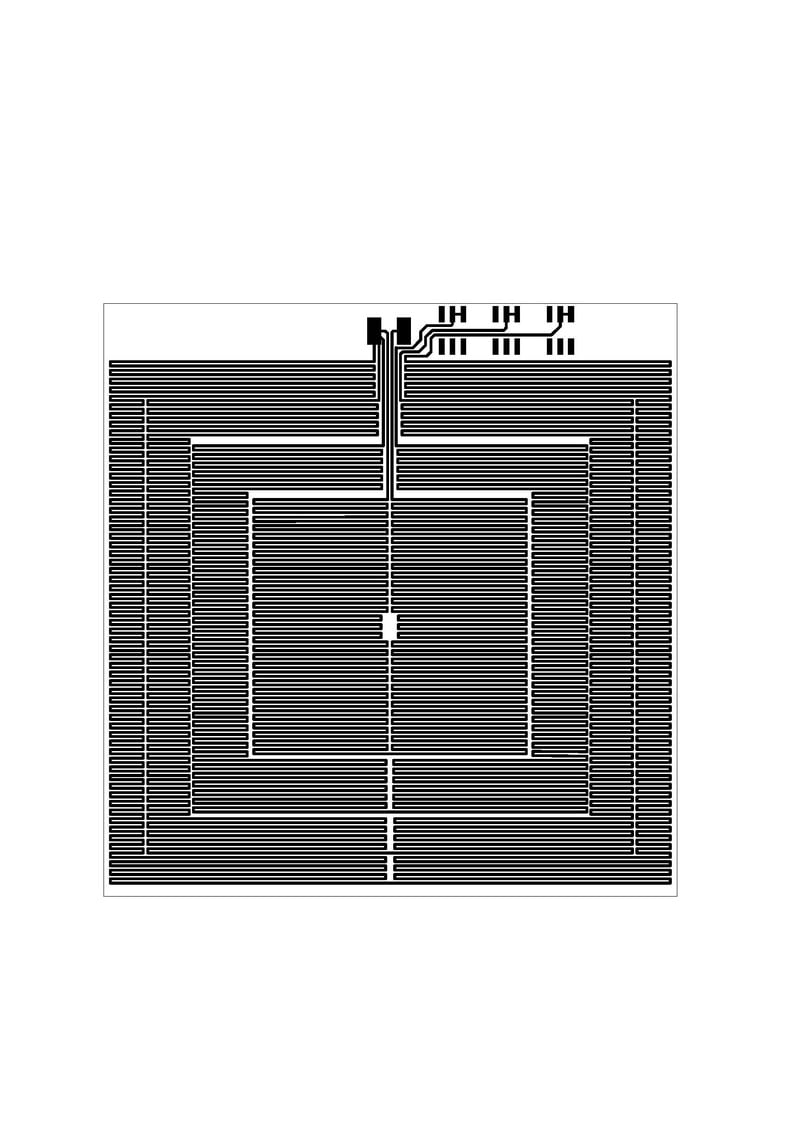
Building from this, I wanted to make similar size PCB heated bed but the one that is adjustable. So I divided the area of the PCB heated bed into four rectangle region such as below with each rectangle has the same area size. Each rectangle area will be filled with the same copper trace length, so each rectangle part will need the same amount of current and generate the same heat.


The innermost rectangle will always be on, while the other three rectangle can be turned on with switches on the side of the PCB. I fabricated the PCB manually and the measured resistance for each rectangle is 3.7 ohm, generating 3.2 amps of current each rectangle for 12 volt supply.
For temperature measurement, only the middle of the Heated Bed will be measured using thermistor. By design, each rectangle should generate the same amount of heat. The thermistor must not be in contact with the PCB Heated bed but to the glass above the heated bed. So I drilled a hole in the middle of wood platform and heated bed. The thermistor will touch the bottom of the glass from the bottom of the printer.

A problem comes up during the testing of the heat bed: the pcb bends because the middle part of the pcb is heated while the outer part don't. So i made a glass holder for the glass and tighten the glass to the wood platform. The glass will force the PCB heated bed against the wood platform, so the heated bed will stay flat. The glass also tightly touch the Heated Bed so the heat transfer process becomes better.

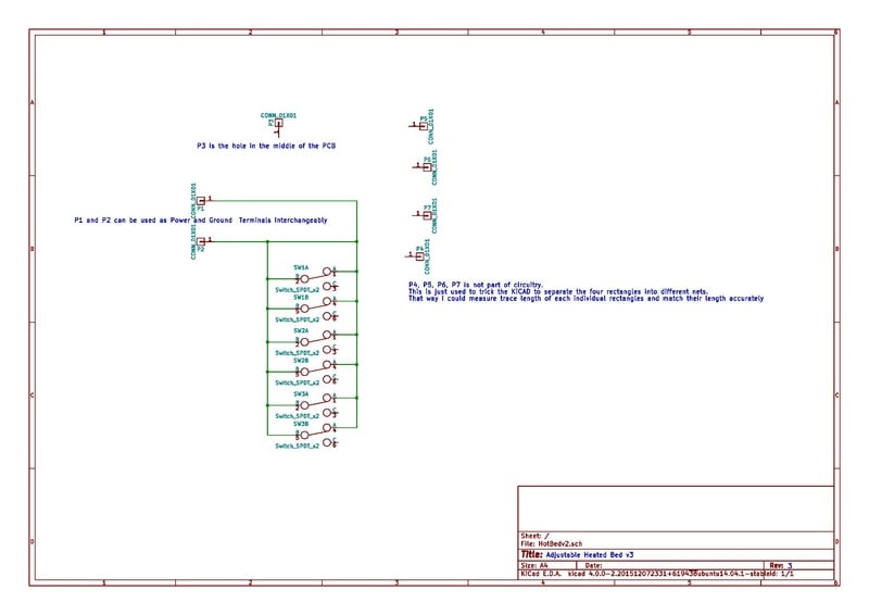
The circuitry for the PCB Heated bed can be seen in the below image. It only include Power and Ground Pad and 3 Switch DPDT. The inner rectangle will always connect to Power and Ground Pad, hence always on. The other three rectangle can be turned on with one DPDT switch for each rectangle. The trace connecting the Switch and Pad will form the heating element with each trace length forming the rectangle is 625 cm. The trace is designed with 0.9 mm trace width, so with copper thickness 1 oz the expected resistance is 3.4 ohm. But due to imperfections in manual PCB etching, the trace width will become less than intended. So as mentioned above the measured resistance becomes 3.7 ohm per rectangle.

Bill of Materials
| Materials | Cost |
|---|---|
| Fabricated Heated Bed | $10 - $100 (Depends if you fabricated it manually or with professional manufacturer) |
| 100Kohm thermistor with Beta = 3950 or similar thermistor with wire of suitable length to connect to the printer controller board | $1 |
| 200 x 213 mm Borosilicate glass | $12 |
| 3 DPDT switch with current rating of at least 3.2 amps each | $3 |
| 18 AWG or bigger wire of suitable length to connect to the printer controller board | $2 |
| three 3-D Printed glass holder using ABS (for high temperature Heated Bed) | $0.5 |
| three #6 x 1/2" sheet metal screw for holding the glass holder | $0.5 |
| $29 - $119 |
Tools
- Athena 3-D Printer
- Soldering station
- Tin
- Drill
- Screwdriver
- Adhesive tape
Assembly Instructions
- The PCB designs files is provided in this page. You can fabricate your PCB Heated Bed manually per the instruction below or with professional manufacturer
- Print the glass holder using the design files provided in this page. Use ABS because it is more resistant to high temperature
- Solder the DPDT Switch and the bigger wire to the PCB
- Drill a hole in the middle of the wood platform and the heated bed. Make sure you drill the position exactly below the position of the hotend at home state
- Place the Heated Bed with the glass on the platform, with the middle of the Heated Bed is exactly below the position of hotend at home state
- Fix the position of the Heated Bed and glass with the glass holder and #6 screw
- Slide the thermistor through the hole in the wood platform from the bottom. The thermistor must not touch the PCB but the glass instead. Fix the position of thermistor with tape
- Connect the bigger wire to the Heated Bed connector of the printer controller board and the thermistor to the Heated Bed thermistor connector of the printer controller board
- Set up the firmware of the 3-D printer to use the Heated Bed and set the parameters of the thermistor correctly.
- Adjustable Heated Bed ready to go !
Settings for Franklin firmware
- Adjust temp = 2 at the top of settings page
- Check the newly available "Bed" check box in the middle section of the page next to the newly available temperature
- Then set R0 = 10Kohm, R1 = infinity, Rc = thermistor value, Beta = thermistor beta, Tc = The temperature at which thermistor value is Rc
- Enable the pins at the bottom of the settings page. The Heated Bed needs pin D12. Check the "valid" check box and click Set button. Do the same with thermistor with pin A6
- Done !
Manual PCB Fabrication
When you only want to fabricate the PCB once, it is recommended to use professional manufacturer service as the process to etch the PCB involve dangerous chemicals and the difference in cost is not much because of initial equipment cost. But if you want to fabricate it multiple times, maybe for experiments, then the manual method will save a lot of cost and time.
Bill of Materials
| Materials | Cost |
|---|---|
| PCB with 1 oz copper thickness 222 mm x 213 mm | $10 |
| 32 % Hydrochloric / Muriatic Acid 950 ml (or at least 300 ml) | $17 |
| 3 % Hydrogen Peroxide 900 ml | $2 |
| Plastic Container at least 300 mm width x 300 mm length with waterproof lid (as etching tank and also to store the chemicals) | $5 |
| Liquid Tin | $15 |
| Metal Polish (to remove copper oxide from the surface of copper) | $10 |
| Ziploc Bag at least the size of PCB | $0.5 |
| A3 Glossy Photo Paper | $25 |
| Acetone | $8 |
| $92.5 |
Tools
- Rubber Gloves
- Breathing mask
- Safety Glasses
- Laser Printer capable of printing A3 size or toner Photocopier
- Electric Iron or PCB Laminator (even better)
- Hacksaw
- Sponge
Instructions
- It is better to cut the PCB to the desired dimension first before etching. Wear a breathing mask and safety glasses. Cut the PCB using a Hacksaw
- Print the PCB Mask File provided in the A3 photo paper using Laser Printer or using normal A3 paper in regular printer and copy to A3 photo paper using Photocopier
- Clean the surface of the PCB using metal polish. Make sure the copper is polished until becomes shiny. It will make it easier for ink to attach to the surface of copper
- Align the printed side of the paper to the copper side of PCB and use the Electric Iron or PCB Laminator to transfer the toner from the paper to PCB. Press the paper to the PCB using Electric Iron evenly throughout all surface of the PCB
- After that, don't remove the paper from the PCB. Rather soak the paper with water and gently scrub the paper from PCB using sponge. This will make sure the ink still attached to the surface of copper
- As in [2] Hydrochloric Acid solution is used because it is more enviromentally friendly. Please read the instruction there on how to etch using the Hydrochloric Acid solution. Do the etching process outside of building. Always wear Rubber Gloves, Breathing mask, and Safety Glasses when unpacking the Hydrochloric Acid, mixing the solution, etching, and storing the chemicals
- After etching, remove the ink from surface of the trace using Acetone
- The trace in PCB needs to be covered in Tin to prevent oxidation. Clean the PCB and insert both the PCB and the liquid Tin into the Ziploc Bag. Shake well until all trace is covered by Tin. This method will preserve liquid Tin so it could be used for another PCB
- Done !
Performance
Energy savings
Energy savings from 0% - 75% compared to original PCB Heated Bed depending on which rectangle is heated up. Each rectangle draws 3.2 amps of current so the whole Heated Bed will draw at most 13 amps of current.
Time to heat

It takes about 10 minutes to heat to the first 90 degree C, another 7 minutes to heat up to 110 degree C
Print result


A test print of ABS on the Heated Bed is conducted with a cylinder and a box 3-D Model. Glue stick is applied on the glass to help with adhesion. As shown above the result does not show any sign of warping.
Adhesion
Printing ABS directly on the glass will not work even if the glass is heated. To help with adhesion, thick layer of glue stick should be applied on the glass. The glue stick should be applied first to the glass, wait for it to dry, and then apply it over and over again to produce thick glue layer. Based on experiment 3 layers of glue stick should be enough.
Files
(Already mirrored)
File:Glass Holder for Heated Bed.fcstd
KiCad Files
Next Step
The next step would probably be building circular Heated Bed for Delta Printer. Right now the PCB Heated Bed consists of 4 different regions. If the regions is increased, the power saving would be increased too. The ultimate goal would be to make the whole printer with Heated Bed operable with 5 amps power supply.