Currently fossil fuels provide more than 85% of the world primary energy demand. As world population increases, global energy demand can only increase. The reality of today's energy crisis demands that increases in fuel burning efficiency are not sufficient to arrive at a sustainable level of fossil fuel consumption. These realities, coupled with increased difficulty and cost of future fossil fuel extraction, make conservation of fossil fuels a major concern.
It is possible to cover the entire global energy demand using renewable sources, but this aspiration requires a completely new energy infrastructure. Additionally, many of these sources fluctuate, thus any renewable energy system must be capable of generating useful energy and to guarantee consistent availability.
Solar water heating offers a renewable energy technology opportunity which could be globally implemented, requires little behavior changes to the end user, and can ultimately reduce fossil fuel consumption. Solar thermal systems can be applied to space heating, water heating, industrial processes, cooling applications or electricity generation.
Background of Solar Technologies[edit | edit source]
The sun is largest energy resource on earth; approximately 3.9x1024 J of energy reaches earth's surface each year, which could cover around 10,000 times the global energy requirements [28]. This abundant source of energy has led to the development of a variety of technical systems to convert solar radiation into a useful form of energy for society, including photovoltaics, solar power plants, and photolysis systems. Indirectly, solar energy creates wind, river current and plant growth, whose energy can also be exploited for use to meet the global energy demand.
Interestingly, the technology for a variety of renewable energies is already available. Historically engineers and scientists developed technologies to increase the quality of life before electricity was implemented into widespread use at the end of the 18th century. These technologies include the use of firewood, wind and water turbines or other alternative technologies.
Today the most widespread use of solar energy is for water heating. Hot water is a fundamental necessity in domestic, commercial and industrial sectors, and can account for 15-25% of energy consumed in homes. Industrially, water heating may account for even more energy. The application of solar energy for domestic water heating rather than space heating is especially appealing due to its consistent need year round.
Background of SDHW Systems[edit | edit source]
Solar water heating is particularly appealing because of its mature development stage. It is the only solar application that had a commercial existence before federal solar energy programs in the early 70's. Because of the quick commercialization of this technology, federal funding of these systems focuses on development of test methods, evaluation and demonstration of new systems rather than design research. Development in solar water heating has largely been completed by the solar industry, making these systems more easily installed than other more complicated technologies.
The first commercial solar water heaters were installed in southern California in the late 1800's, first as roof-mounted blackened tanks with no insulation and later in conjunction with a wood stove to provide a continuous source of hot water. Later designs used glazed tubular solar collectors separated from elevated storage tanks in thermosyphon arrangement, a configuration which is still used in mild climates. Auxiliary heaters were often installed in these systems to ensure a continuous hot water supply. Later, heat exchangers were also implemented into these systems as a method of freeze protection. California use of solar water heaters declined in the 1920's and 30's due to increased availability of natural gas and low electricity prices.
Around the same time, population increases in the Miami area prompted increased use of solar water heating systems; it is estimated that over 50,000 systems were manufactured and sold in this time period. The most common system used in the Florida was the "SunCoil," which consisted of a copper absorber with insulated housing connected to residential plumbing. These systems flourished until the early 1940's when the government instituted a freeze on non-military use of copper.
Following World War II, the introduction of washing machines and dishwashers further increased the domestic hot water demand beyond what a solar water heating system could provide. These factors, along with the introduction of mass-produced electric water heaters and low fuel costs contributed to the decline of solar water heaters in the US in the 1950's.
While the US saw a decline in the application of solar water heating around the middle of the 20th century, international increases in electricity prices spurred development of new solar water heating designs around the world. Government policy in Israel in the 1950's required the installation of thermosyphon solar water heaters in new housing projects. A similar level of wide-spread commercialization of solar water heaters was achieved in Australia and Japan in the 1970's.
In the United States, a renewed increase in the manufacture and sale of solar water heaters began after the oil embargo of 1973. Many companies began manufacture of flat-plate solar collectors, and by 1979 solar water heating systems had were being installed at a rate of nearly 50,000 systems per year, a number which increased two or three-fold by 1984 (DOE).
The past decade has shown significant increase in the use of solar domestic water heating systems due to the global pressures to reduce greenhouse gas emissions as well as the quest for sustainable energy solutions. Today, solar water heating is most widely practiced solar technology; an estimated 500,000 – 800,000 residential solar water heaters are installed in the US today. While these numbers are encouraging, less than 1% of residential and commercial establishments in the United States are provided with solar heated water. This, compared to an approximated 10 million systems installed in China and high installation rates in Europe, India, Egypt and Turkey, leaves a wide berth for improvement. Current systems are reliable as a primary water heating method, however widespread use is limited by market demand, which will not likely improve until conventional fuel prices increase significantly.
Current Technologies[edit | edit source]
The most basic solar water heating system consists of a tank filled with water that is exposed to sunlight in warm temperatures. The water inside the tank is heated up and can be connected to residential plumbing. While this set-up is useful to understand a basic solar water heating system, it is too simplistic for realistic use. More complex systems have been designed which separate the collector from the thermal storage tank.
Solar domestic hot water systems could reduce total household energy use by 50% [10]. Currently, around 100MW of solar water heating systems have been installed in the United States. Comparing this value to installation rates in Europe (2000MW) and China (15000MW), it is evident that the solar water heating market in the US is not yet competitive with the rest of the world. System costs in the United States are limited by lack of retailers and a knowledgeable service sector. Total life cycle costs are narrowly cost-effective compared to the cost of a traditional water heating system.
System Components[edit | edit source]
Every solar domestic water heating system consists of the same basic equipment. A solar collector collects solar radiation and concentrates the thermal energy to a thermal reservoir. Piping and other structural equipment are also required for system functionality. More complicated designs may include circulation pumps, sensing and controls, heat exchangers with a recirculating thermal fluid, auxiliary heating capabilities or other sensor-regulated capabilities.
Collectors[edit | edit source]
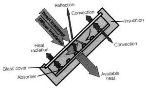
The purpose of the collector to collect, concentrate and convert solar radiation to useful thermal energy. An absorber converts sunlight to heat which is then transferred to the domestic water supply or to a separate recirculating thermal fluid. Absorber material is typically metallic, such as copper, steel or aluminum, which is then coated to improve heat absorption. This can be accomplished through the use of black lacquer. The use of more efficient other selective coatings can help reduce losses at an increased cost.
The absorber is protected by a transparent cover to minimize convective and radiative losses to the environment and to serve as a protective barrier. The covering of the collector can be described in terms of reflectance ρ, absorbance α and transmittance τ. Generally, low reflectance and high absorbance and transmittance glass or plastic is desirable for highly efficient collectors. Low-iron solar glass is often used because of its high transmittance and durability to environmental hazards.
The absorber is contained in a housing which is highly insulated on the back and sides to minimize heat loss. The housing and binding materials must be temperature-resistant and the glass plate must be properly sealed to the collector housing to contain heat and prevent dirt and humidity from entering the chamber.
To properly understand collector performance, conversion efficiency from solar radiation to useful heat is considered. Solar irradiance E is converted to heat Q through the transparent covering with transmittance τ onto a collector area Ac. Overall conversion in limited by reflection ρ and convection to the atmosphere. Overall collected heat is given as:

Generally radiative losses are minimal compared to reflective and convective losses and can be neglected. The implementation of a vacuum in the collector can minimize convective losses.
Reflective losses can be quantified by knowing the reflectance from the radiation passing through the glass covering. Maximum efficiency for a particular system is achieved by eliminating convective and radiative losses, and is thus a function of reflective losses only. Maximum collector efficiency is given by:

Taking into account convective and radiative losses, which largely depend on temperature difference between the collector interior and the ambient environment, yield actual collector efficiency as:

Other environmental effects can be included in the analysis above as loss coefficients, and will account for additional losses.
Here, it is important to note that collector efficiency is a function of cover properties, collector area, temperature difference, and solar insolation. A greater temperature range between the absorber and the environment increases cycle efficiency, but also increases thermal losses. As a result, overall temperature range must be monitored to ensure appropriate process efficiency, and collector materials must be able to withstand a substantial temperature range.
The most common types of collectors for residential solar water heating are flat-plate collectors, evacuated flat-plate collectors and evacuated-tube collectors.
Flat-plate Collector[edit | edit source]

A flat-plate collector is the most simple collector design, characterized by a flat absorber plate over metal tubes containing the domestic water supply or a thermal fluid as found in Figure 1.
Despite lower conversion efficiencies than other collector designs, the appeal of flat-plate collectors lies in the simplicity of the design. The major disadvantage to flat-plate collectors is the requirement of a storage tank due to their small size; these collectors can quickly overheat if the water inside is not continuously replaced.
Evacuated Flat-plate Collector[edit | edit source]
An evacuated flat-plate collector is an improved version of the standard flat-plate collector, which minimizes convective losses by implementing a vacuum in the collector chamber. Atmospheric air pressure on the glass plate necessitates the installation of supports between the back of the collector and the front cover to keep the unit from collapsing. The vacuum requires occasional maintenance as the seals on the system are subject to some losses.
Evacuated Tube Collector[edit | edit source]

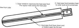
] Evacuated tube collectors further develop the concept of an evacuated flat-plate collector by embedding a metal absorber sheet with a heat pipe in the middle in an evacuated glass tube. A temperature-sensitive thermal fluid is heated and allowed to vaporize inside the tube. The fluid rises to a heat exchanger and condenser system to capture the heat from the medium, then falls back to the bottom of the tube when it can be re-vaporized. This type of system depends on geometry for proper functionality, thus the inclination angle of evacuated tube collectors is particularly important.
Evacuated tube collectors are especially appealing in that the vacuum inside a glass tube is easier to maintain than that of a flat-plate; their geometry allows them to resist ambient air pressure, eliminating the need for additional supports. Evacuated tube collectors can more effectively capture heat from solar radiation requiring a smaller collector area than comparable flat-plate collectors.
The major limitation to evacuated tube collectors is increased cost. Materials and construction costs are higher than for other collector types, and the system as a whole may require additional support equipment. For example small molecules such as atmospheric hydrogen can enter the system, eventually eliminating the vacuum. This can be remedied by installing "getters" to absorb hydrogen over time, or by using a vacuum pump to replenish the vacuum from time to time which add to collector cost.
Example: Roof-integrated Collector [17][edit | edit source]
One new collector design is presented by Luis Juanicó of the Bariloche Atomic Center in Bariloche, Argentina. The system takes advantages of the relationship between roof-mounted collectors and the roof itself. The concept is based on expanding collector area to the entire roof, allowing for the additional potential for space heating to a water heating system.
The proposed system is an evolved version of the SkyTherm, originally proposed by Harold Hay in 1977. The SkyTherm consisted of water bags mounted over a simple metallic roof, which were protected by a folding insulated cover. The cover served to collect and store solar energy in the winter, and perform the opposite in the summer. Generally, the SkyTherm is considered to be the foundation of all roof collector designs that exist today.
Today, most roof collectors consist of a metallic roof composed of corrugated or trapezoidal metal sheets which serve as the absorber and contain piping with domestic water. Recent window glazing and piping technologies have helped to reduce precipitation leaks of these systems, however the high cost to achieve adequate thermal insulation limits the appeal of these systems.
The system proposed by Juanicó uses a metallic waterproof base with a cover of double-layer glass. A shallow water pond is encased between the metal base and the glass, and is connected with piping to a thermal storage tank. Additional components may include pumps, auxiliary heaters or a rolling awning (such as that proposed by the SkyTherm) to provide an additional insulation chamber. This system can be applied to an inclined roof simply by ensuring the main water chamber is completely airtight.
The proposed system functions by collecting solar thermal energy during the day and storing it during the night; the insulating cover can be closed at night to reduce thermal losses. Ideally, the thermal energy available from an extended collector surface area is plenty sufficient for domestic hot water, and may also be applicable to space heating and cooling.
The proposed roof-integrated collector is that it eliminates the need for a thick insulation layer due to the sufficient insulating properties of the water pond. Temperature distribution throughout the collector water is gradual, resulting in more evenly-distributed thermal properties of the water. Because this system was proposed from a roof standpoint rather than a collector standpoint, it is applicable to a variety of climates and roof configurations.
Thermal Storage[edit | edit source]
Some form of thermal storage is required for all solar water heating systems. This can be integrated with the collector, however most collectors are too small to store enough water to meet the hot water demand of a household. Thermal storage tanks must have the physical and thermal capacity to store sufficient water to meet domestic hot water demands over a designated period of time, and are insulated to retain as much heat as possible when not in use.
Thermal storage systems can be installed as single or multiple tank configurations; generally, single tank systems are more efficient than multiple tank systems as long as the unit is stratified and well-insulated. Tank stratification is used to reduce collector inlet temperature, which increases thermal efficiency of the collector. Ultimately, appropriate thermal storage configuration is determined by application, load demand and available solar resource to meet necessary hot water requirements of a particular site.
In general, storage volume should be 1.5-2 times the daily hot water demand to account for times of limited solar radiation. Insulation is an important consideration to limit heat losses; best practice entails insulation with a thickness of at least 100mm and thermal conductivity of 0.04W/mK or lower [28]. Because heat loss to the environment is highly proportional to residence time in the tank, it is important to consider how long heat must be maintained in the unit. A high surface area to volume ratio of the tank can further contribute to thermal losses.
Mathematical calculations can be used to estimate thermal storage capacities, however accurate results may be difficult to achieve due to constant heat addition and subtraction; complex computer algorithms are the only method to accurately estimate variation of water temperature inside a storage unit. For simplicity, calculations here are limited to the assumption of an average water temperature throughout the tank rather than accounting for tank stratification. When necessary, tank stratification can be accounted for by dividing the tank into layers of varying heat. The simplified heat storage capacity of a thermal storage tank is then given by:

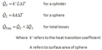
Thermal losses are calculated by the following

It is important to note that deviation between optimal and actual storage temperatures can affect the running characteristics of a water heating system. If storage temperature is greater than desired load temperature, an appropriate quantity of hot water from the storage tank must be discharged and mixed with cold water to arrive at desired load temperature and flow rate. If storage temperature is the below the desired load temperature, additional heat requirements must be met by an auxiliary heater. In all cases, the cold water inlet is at the bottom of the tank and hot water exits the system at the top of the tank.
Piping[edit | edit source]
Collector flow rate is influenced by pipe geometry; pipe diameter can be found knowing the heating requirements from the collector and taking into account associated thermal losses. Flow rate calculated as a function of required heat is given by:

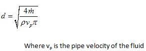
Required pipe diameter can be calculated by:

Thermal losses from piping, including circulation and heat-up losses, should be considered when evaluating a solar water heating system. Circulation losses refer to heat-loss to the environment as a function of total piping length and time, governed by:

Heat-up losses result from the energy required to heat up the pipes and the heat transfer fluid after they have cooled when the system is out of service. These losses can also occur at stop valves, pumps and other required piping components, and can be described for n-cycles by:

Additional Equipment[edit | edit source]
There is a variety of additional equipment that can be included in a basic solar water heating system to improve performance. These include pumps, controls and sensors, heat exchangers, and auxiliary heat sources, as well as a multitude of other options.
Pumps and Blowers[edit | edit source]
Pumps and blowers can be installed where there is an auxiliary power source to improve system circulation and eliminate the need for a height differential between the collector and thermal storage units. Recirculating pumps can also be used as a method of freeze protection. While the installation of pumps and blowers require additional power, system efficiency can be significantly improved and the system can potentially be installed in regions where otherwise impossible.
Controls and Sensors[edit | edit source]
Pumps and blowers can be installed where there is an auxiliary power source to improve system circulation and eliminate the need for a height differential between the collector and thermal storage units. Recirculating pumps can also be used as a method of freeze protection. While the installation of pumps and blowers require additional power, system efficiency can be significantly improved and the system can potentially be installed in regions where otherwise impossible.
Heat Exchanger[edit | edit source]
Heat exchangers may be installed for indirect solar water heating to prevent freezing in cold regions and improve thermal efficiency. Generally, a thermal fluid in a closed loop is heated in the collector, and heat is transferred to a potable water source for domestic use. While these systems may cost more and require extra maintenance, their versatility make them appealing, particularly in regions where freezing is a concern.
Auxiliary Heat Source[edit | edit source]
Heat exchangers may be installed for indirect solar water heating to prevent freezing in cold regions and improve thermal efficiency. Generally, a thermal fluid in a closed loop is heated in the collector, and heat is transferred to a potable water source for domestic use. While these systems may cost more and require extra maintenance, their versatility makes them appealing, particularly in regions where freezing is a concern.