
The Solar Charging Station is a solar powered system that charges cell phones and other small electronics via a USB port.The purpose for the charging station is to educate the students and staff of Redwood Coast Montessori of solar power. It was designed in the Cal Poly Humboldt Engineering 215 Fall 2014 by the team Las Calabasas De La Revolucion.The team is comprised of Jillian Freiheit, Julia Gomez, Javier Hinojosa, and David Rivera.
Background[edit | edit source]
The client for our project is Redwood Coast Montessori (RCM). It is a public charter school located next to the Manilla Sand Dunes in Arcata, CA. Founded in 2005, the program started out with one classroom on a traditional public school campus in Eureka, CA. In June 2012, the Arcata School District approved Redwood Coast Montessori's charter application to become a K-8 independent public charter school beginning on July 1, 2013. The Montessori style of teaching acknowledges that children in early childhood need to develop their cognitive abilities through experiences with their senses and different materials. As they grow, Montessori students at an elementary age apply what they have learned to real world experiences.
Problem Statement[edit | edit source]
Redwood Coast Montessori has two 100 watt solar panels but has no use for them.
Objective[edit | edit source]
The objective is to implement a functional solar powered system that educates the students and staff of Redwood Coast Montessori, as well as the public, of solar power, solar panels, and the importance of solar as a renewable energy.
Criteria[edit | edit source]
Together with the client our team came up with a set of criteria to decide on our final design. The criteria for the project are weighted on a scale of 1-10. Ten being the most important and 1 being the least important.Safety is defined as, no serious harm to students and staff; likeliness to cause electrical burns or damage to persons or structures. Maintainability is defined as the ability to be maintained by school staff; the extent to which the project requires attention from staff. Educational value is defined as the extent to which the project is thought-provoking; how well it educates the students, staff, and the general public of solar power. Aesthetics is defined as how aesthetically pleasing the design is and how well it blends with natural environment. Cost is defined as the total amount of money needed to build and maintain the design. Light pollution is defined as the extent to which it pollutes the night sky with light radiating from light sources. Theft is defined as susceptibility to being stolen. Usefulness is defined as the frequency it is used by the children, staff and public.
| Criteria | Weight (1-10) |
|---|---|
| Safety | 10 |
| Educational Value | 10 |
| Aesthetics | 8 |
| Theft | 8 |
| Usefulness | 7 |
| Cost | 6 |
| Maintainability | 5 |
| Light Pollution | 3 |
Description of the Final Project[edit | edit source]
The final project is a solar-powered charging system for powering small devices using a USB socket (2x 5V/2/1A Waytek A13-208[1]). Energy is collected by a 100 watt solar panel mounted to the roof of the school.
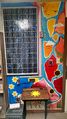
The energy collected by the panel is directed inside the copy room to a charge controller, which regulates the power flow, and then sent to a 12 volt, 40 amp hour battery to be stored for later use. The battery connects to a USB port mounted to a vintage school desk which was purchased from a local community member. This USB outlet is to be used by the students, staff, and community. Alongside the outlet, there is a mural, an educational display, and a display solar panel. The mural is an artistic depiction of solar power painted onto the wall of the copy room. The educational display is a brief description of the design and a simple explanation of solar power systems. The display solar panel is identical to the panel on the roof, and functions as a back-up panel as well as an educating device.
-
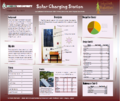
Fig 1: Las Calabasas de la Revolucion Solar Charging Station poster
-
450px

Costs[edit | edit source]
| Quantity | Material | Source | Retail Price ($) | Price Paid ($) |
|---|---|---|---|---|
| 1 | Solar Charge Controller | SunForce | 32.87 | 32.87 |
| 1 | USB Outlet | Waytek, Inc. | 11.00 | 11.00 |
| 1 | Battery | Broadway Medical | 116.00 | 20.00 |
| 1 | Wire | Ace Hardware | 47.20 | 47.20 |
| 2 | Solar Panels | CCAT | 300.00 | Donated |
| 1 | Grounding Clamp | Ace Hardware | 5.99 | 5.99 |
| 10 | Grounding Wire | Ace Hardware | 6.90 | 6.90 |
| 1 | Grounding Rod | Ace Hardware | 16.99 | 16.99 |
| 1 | Conduit | Ace Hardware | 2.99 | 2.99 |
| 1 | Desk | Craigslist | 35.00 | 35.00 |
| 4 | Stainless Steel Bolts | Ace Hardware | 2.00 | 2.00 |
| 4 | Stainless Steel Nuts | Ace HArdware | 1.60 | 1.60 |
| 1 | Junction Box | Ace Hardware | 2.49 | 2.49 |
| 1 | Multimeter | Ace Hardware | 32.99 | 32.99 |
| 1 | Velcro | Pierson Building Company | 7.98 | 7.98 |
| 1 | Metal Lightswitch Box | Pierson Building Company | 2.79 | 2.79 |
| 1 | Plastic Lightswitch Box | Pierson Building Company | 0.85 | 0.85 |
| 2 | Disconnect Switch | Pierson Building Company | 1.70 | 1.70 |
| 2 | Fuse | Ace Hardware | 5.98 | 5.98 |
| 2 | Fuse Holder | Ace Hardware | 7.98 | 7.98 |
| Total Cost | $665.92 | $269.92 | ||

Testing Results[edit | edit source]
Once the installation of the solar PV system at Redwood Coast Montessori was complete, the team was successfully able to verify the working condition of the system. After turning on both the breakers, the final test was to turn on the loads, which successfully worked with both charging ports occupied.
How to build[edit | edit source]
After obtaining all required materials, make sure the loads are properly wired.
Wire the battery together, then connect to the charging station.
Wire a disconnect switch so that the charging station can be left connected to the battery without slowly draining and depleting the battery. Another disconnect switch is needed in between the charge controller and solar panel.
NOTE: This step is specifically for this project, and may not apply to other systems.
Wire the PV panel by connecting a 10 amp fuse on the positive wire and another 10 amp fuse on the negative wire.
Connect the positive wire from the PV panel to the disconnect switch, then into the charge controller. Make sure the disconnect switch is switched to the off position.
Connect the negative wire from the PV panel into the charge controller.
Connect the positive wire from the batteries to the disconnect switch and charging outlet on charging station, then into the charge controller. Make sure the disconnect switch is switched to the off position.
Connect the negative wire from the batteries into the charge controller.
Flip the disconnect switch to the on position, and then do the same for the other disconnect switch on the charging station. Plug in the loads to see that the system works.
NOTE: Depending on which model charger controller you are using, the order of the wiring will vary. It is important that you follow the installation instructions stated in your charge controller manual.
How to use Solar Charging Station[edit | edit source]
To use the charging station, first flip the disconnect switch, above the charge controller, to the "on" position. Next, lift the lid of the desk and flip the second disconnect switch to the "on" position. Once the second disconnect switch is put in the "on" position, inside the charging station, the charging port will emit a blue light indicating electricity is flowing through and the charging station is ready to charge devices.

How to maintain[edit | edit source]
In order to keep the system operating and running efficiently, periodically check the system. The periodic checks involve inspecting the wires for all aspects of the system, and monitoring the solar charge controller. The panels must also be cleaned once a month, or after a storm in order to maintain panel efficiency. The batteries must also be replaced after their lifespan has ended.
Troubleshooting[edit | edit source]
Below are details of some problems that may arise in the photovoltaic system and solutions for these problems:
| Problem | Solution |
|---|---|
| If the system is not providing power for as long as usual it is due to the batteries becoming worn down. | To solve this issue simply replace the battery and connect the wires to the battery correctly. |
| If charge controller is overcharging battery (verified by measured current through the controller) it may be due to the photovoltaic panel positive and Battery positive wires have been swapped. | To solve this issue verify the voltage on photovoltaic panel terminal and Battery terminal are from the correct sources. |
| If the system does not work it may due to possible wire faulting and/or one or more of the appliances are faulty. | To solve this issue thoroughly investigate wires for any visible damage and replace if needed and/or replace one or more components of the system if needed. |
Discussion and next steps[edit | edit source]
The top two criteria for this project are safety and educational value. Being equipped with a grounding rod, multiple fuses, and a charge controller, this project is safe for users from children to adults. Located within the charge controller is a watt meter. From this meter, students will be taking daily measurements of the amount of energy being produced by the system. To bring even more educational value to the project, it is equipped with multiple educational plaques which: explain how solar works, briefly describe how each component contributes to the system and explain the advantages of solar as a renewable energy. Not only can this project be used by the students and staff of Redwood Coast Montessori as well as the community, it is an effective learning tool that makes all of our futures a brighter one.