
CAN YOU WorKIT (shown in Figure 1) is an educational kit, designed in the Cal Poly Humboldt Engineering 215 class, targeting students at the high school level in order to teach about conservation of energy. The kit is supplied by the Redwood Coast Energy Authority to teachers upon request.
RCEA Educational Kits[edit | edit source]
CAN YOU WorKIT is designed to have students assemble and operate hand crank electrical generators in order to understand the connection between work and energy. Through the powering of multiple devices in conjunction with an activity worksheet, the students will observe the amount of work that goes into powering every day appliances and in turn apply their understanding towards the conservation of energy.
Objective and Criteria[edit | edit source]
The objective of CAN YOU WorKIT is to create a fun, interactive, reusable and transportable educational kit to promote energy conservation through the Humboldt County schools. This toolkit is geared towards grade levels 9-12.
Criteria[edit | edit source]
The criteria was developed by the group, and reviewed by the client. The criteria was implemented to wiegh the strenghts and weaknesses among the alternative solutions developed. The criteria is listed in order of most important to least important.
- Educational Value - The educational value criteria refers to the material and procedures of the kit. The Educational Value how educational a solution is expected to be, given the high school academic level.
- User Friendliness - The user friendly criteria weighs the ability of students and teachers to use the kit properly and with ease.
- Fun - The fun criteria is used to gauge the level of entertainment possessed by a solution.
- Transportability - The solutions will be weighed on the ability to be transported from RCEA to the high school, transportability is a requirement so the ease of transport will be weighed.
- Durability - The durability criteria will rate the ability of the proposed solution to withstand regular use without losing its functionality.
- Physical Interactivity - The physical interaction criteria measures the level of hands on involvement possessed by each solution.
- Magnitude of Impact - The magnitude of impact criteria will weigh potential energy savings compared to other solutions.
- Safety - The safety criteria encompasses how much risk of injury is present in the proposed solution.
- Teamwork - The teamwork criteria will weigh the amount of time students spend interacting with one another to perform a process.
- Aesthetics - The aesthetics refers to the physical appearance of the kit, this criteria will weigh the visually pleasing aspects of the proposed kit.
- Local relevance - The local relevance criteria will weigh the applicability of the proposed solution to the local community, most notably Humboldt County.
- Cost - The cost refers to the expense to implement and maintain the kit. These expenses include the materials to build the kit, the materials that will be inside of the kit, the projected maintenance costs, and the time required to complete the educational kit.
Overview[edit | edit source]
The final design solution includes hand cranked electrical generators to be

assembled in class and used by students in groups. There are six boxes in the kit along with a few other devices and activity worksheets (shown in Figure 2).
Materials Found Within Each Box[edit | edit source]
- 1 Set of Instructions
- 1 Hand Drill
- 1 Crank Arm
- 1 Volt Meter
- 1 LED Light
- 1 Set of Wires
Curriculum[edit | edit source]
The kit contains copies of a worksheet used to integrate the hands on work with energy conservation. Each student is given a worksheet where they can measure and calculate voltage, wattage, and dollar value of energy produced based on local energy cost. The worksheets guide readers through different calculations, explain how to do them and what they mean. The calculations are intended to give perspective on daily energy use. Understanding the relationship between work and electrical energy can encourage students to practice energy conservation.
- This is a copy of activity worksheet.
Instructions[edit | edit source]
The following steps correlate to Gallery 1 shown below.
* Step 1 - Insert red taped end of hank crank (90 degree bent side) into the chuck jaws of the drill and tighten.
* Step 2 - Identify positive and negative terminals as labeled on the hand drill.
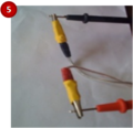
* Step 3 - Attach wire to the positive and negative leads within the drill. NOTE: RED to POSITIVE and BLACK to NEGATIVE.
* Step 4 - Hook up volt meter leads. Insert black lead into black volt meter socket (COM). Insert red lead into red volt meter socket. Turn dial to 20 volt DC (direct current) setting.
* Step 5 - Attach free end of the wire to volt meter leads: Red alligator clamp to red volt meter lead and Black alligator clamp to black volt meter lead.
* Step 6 - Grip drill firmly while holding the trigger down. Place free hand on the hand crank and rotate.
* Step 7 - Read volt meter and record highest voltage. Using this value, calculate wattage, kilowatt hours, and Dollar value produced.
* Step 8 - Un-hook wires from volt meter, and hook the wires to the light. Set up with the light oriented as shown in the picture. Clip the red wire on the positive terminal (right side) of the light and the black wire to the negative terminal (left side). Crank the drill to power the electronics.
Gallery 1: Steps of Assembly[edit | edit source]
-
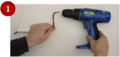
Insert red taped end of hank crank (90 degree bent side) into the chuck jaws of the drill and tighten.
-
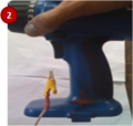
Identify positive and negative terminals as labeled on the hand drill.
-
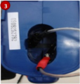
Attach wire to the positive and negative leads within the drill.
-
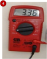
Hook up volt meter leads. Insert black lead into black volt meter socket (COM). Insert red lead into red volt meter socket. Turn dial to 20 volt DC (direct current) setting.
-
Attach free end of the wire to volt meter leads: Red alligator clamp to red volt meter lead and Black alligator clamp to black volt meter lead.
-
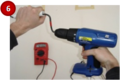
Grip drill firmly while holding the trigger down. Place free hand on the hand crank and rotate.
-
Read volt meter and record highest voltage. Using this value, calculate wattage, kilowatt hours, and Dollar value produced.
-
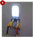
Un-hook wires from volt meter, and hook the wires to the light. Set up with the light oriented as shown in the picture. Clip the red wire on the positive terminal (right side) of the light and the black wire to the negative terminal (left side). Crank the drill to power the electronics.


How to Replicate the Kit[edit | edit source]
Setting up this kit involves some preparation, but most of the setting up is done by the students. Required materials for one generator include: one DC hand drill, one and a half feet of 1/8" steel rod, one half foot piece of PVC pipe (any width), three feet of 18 gauge speaker wire, four alligator clips, electrical tape, and some way to label charges.
-
Figure 3: Making the Hand Crank
-
Figure 4: Taped Electrical Leads
-
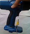
Figure 5:Black to Negative(-)
-
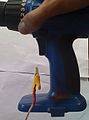
Figure 6:Red to Positive(+)


Making the hand crank is the most labor intensive portion of the construction. The steel rod comes in three feet pieces, and must be cut to be used as a crank. Figure 3 shows the arm being cut with a dremel, but a hacksaw can be used instead. The steel rod must be bent with two right angles, giving the crank a moment arm. This process can go more smoothly by heating the rod, making it easier to bend. Bending can be done with any sort of vice clamp and force. Once the two bends have been made, the PVC pipe can slip onto the handle. It is important that the rod be cooled before the pipe is attached. Once the pipe is on the new crank arm, the straight end can be bent to secure the pipe and keep it from falling off. To reduce slipping, the end of the arm that goes in the drill can be given a flat edge for the drill to grip, as seen in Figure 7.
Making the connection wires requires three feet of 18 gauge speaker wire, four alligator clips, and electrical tape (red for positive lead and black for negative leads). The ends of each length of wire needs the sheaths removed with wire cutters ¼ inch to ½ inch from the tip. Each wire lead needs to be twisted in the clockwise direction tightly and inserted into the alligator clips. With wire lead aligned into the alligator clip, the base of the clip needs to be clamped down creating a secure connection. After the secure connection is made a corresponding piece of electrical tape is wrapped around the base of the clip and tip of wire as shown in Figure 4. This is done to avoid electrical shorts and to identify positive or negative leads.
The generator at this point is complete and functional and can be assembled with the previously listed instructions. The next stage of development is the labeling of the hardware. The positive and negative terminals can be identified by observing the battery labels, and where they go. Corresponding " + "and " – " signs are labeled on outside of drill on bottom of handle as shown in Figure 5 and Figure 6.

Cost[edit | edit source]
Design Time Input[edit | edit source]
The following pie chart represents the time spent on the design project, time spent in each phase is displayed as well as total time. The time spent on the entire design process for the educational kit is also broken into percentages, displayed the proportion of time spent on each phase. The pie chart (Figure 8) represents time spent for the entire team.
Figure 8: Time Invested[edit | edit source]

Implementation Cost[edit | edit source]
Below is a table (Table 1) showing the cost involved with creating the educational kit. The table includes a breakdown of materials involved, quantity of materials, and cost of materials. Materials involved in finalizing the kit include: items in the kit, materials used for construction, and materials used for testing. Not all materials purchased ended up in the final kit.
Table 1: Materials and Expense[edit | edit source]
| Materials | Unit Cost($) | Quantity | Subtotal($) | Tax($) | Total($) |
| 18 Volt Electric Drill | 19.99 | 6 | 119.94 | 10.79 | 130.73 |
| Mini-Stake Solar Light | 4.49 | 1 | 4.49 | 0.40 | 4.89 |
| 2" Alligator Clip | 2.99 | 12 | 35.88 | 3.23 | 39.11 |
| 18 Gauge Lamp Wire | 0.47 | 18 | 8.46 | 0.76 | 9.22 |
| 36" x 7/32" Steel Rod | 3.49 | 3 | 10.47 | 0.94 | 11.41 |
| Hack Saw Blade | 1.99 | 1 | 1.99 | 0.18 | 2.17 |
| 18 Gauge Lamp Wire | 0.49 | 9 | 4.41 | 0.40 | 4.81 |
| Alarm Clock | 5.00 | 1 | 5.00 | 0.45 | 5.45 |
| Connect Four | 2.00 | 1 | 2.00 | 0.18 | 2.18 |
| Cassettes | 1.00 | 3 | 3.00 | 0.27 | 3.27 |
| Walkman Cassette Player | 5.00 | 1 | 5.00 | 0.45 | 5.45 |
| Volt Meters | 7.99 | 7 | 55.93 | 5.03 | 60.96 |
| Spray Paint | 2.29 | 3 | 6.87 | 0.62 | 7.49 |
| Paint Pen | 5.99 | 1 | 5.99 | .54 | 6.53 |
| Heat Skrink Tube | 10.49 | 1 | 10.49 | .94 | 11.43 |
| Total | $310.56 |
|---|
Maintenance Cost[edit | edit source]
When designing the kit, the goal was to keep maintenance cost low. Materials included are abundant enough that in the case of part failure, replacement is not immediately crucial. To maintain the kit in its original state, Table 2 shows the projected maintenance cost over a five year period.
Table 2: Projected Maintenance[edit | edit source]
| Item | Expected Replacement Per 5 Years | Cost Per Item($) | Tax Per Item($) | Expected Cost Per 5 Years($) | Expected Cost Per Year($) |
| Drill | 1 | 19.99 | 1.80 | 21.79 | 4.36 |
| 3 ft Wire | 2 | 1.47 | 0.13 | 3.20 | 0.64 |
| Clips | 2 | 2.99 | 0.27 | 6.52 | 1.30 |
| Electronics | 4 | 7.00 | 2.52 | 30.52 | 6.10 |
| Total | $62.03 | $12.40 |
|---|
Results[edit | edit source]
When testing the hand crank generators three significant issues arose. These issues were the strength of the material utilized for the hand crank, the length and angle of the hand cranks, and the incorporation of items to power without blowing the fuses or burning the wiring within.
The first hand crank that was tested was a three foot steel rod that was composed of five angles. The design of this rod was to allow the user the ability to use two hands while cranking the generator while another student held the drill. During the testing of the rod it was realized that minute electrical generation was occurring due to the large spin radius. The increased spin radius greatly decreased the amount of revolutions the user could generate in a given time.
The second hand crank that was tested was a metal coat hanger that was bent and inserted into the chuck jaws. The coat hanger was the dimensions that we used to model our current hand cranks. The coat hanger generated much more electricity, and required far less input from the user compared to the first hand crank. The metal of coat hanger turned out to be too malleable to be used as the final hand crank material, while the hanger produced significant amounts of electricity the hanger bent and twisted too easily, which also created a loss of energy from the user to the drill.
The first item we attempted to power was a single LED light; the surge of electricity from the drill immediately burnt the internal wiring of the light. At this point we began to monitor with volt meters the average output of the generator and the maximum surges we were witnessing. We used this information to select the items we would include in the box. We check the voltage the device requires from batteries and compare it to the average output of the drill. We also used the average electrical outputs to determine how many generators in series it would take to power larger devices.
Authors[edit | edit source]
The final Energy Conservation Educational Kit document.