
Team[edit | edit source]
Pierce Jensen' Electrical Engineering, Mechanical Engineering,
Andrew McMichael Electrical Engineering
Isabella Kesler Mechanical Engineering,
Project[edit | edit source]
This page is dedicated to the design and development of a parametric D-Sub Connector. This project would allow for replacement connectors to be made easily and cheaper than buying new ones when they break. The parametric aspect would allow someone to change the size and shape of the connector simply by changing the number of pins in the connector. This project will be performed by the students listed above as a part of the MY4777 2016 Class.
Model[edit | edit source]
Concept
The Parametric D-Sub Connector will be made up of a 2 piece case, connector body, and pins. The only parts of the connector that will not be 3-D Printed are the pins. The pins will be pushed through the pre-printed holes and the attached wires will be fed through the exit of the connector. The size of the connector will be easily modified with the changing of several values in the source code. The connector casing and body are also customized based on the number of pins the user wants.
The parts can be found at the NIH Printing repository here.
Bill of Materials
- Connector Casing Top
- Connector Casing Bottom
- Connector Body
- Male Connector Pins
- Purchased from Digikey Male Connector
- Female Connector Pins
- Purchased from Digikey Female Pins
Estimated Cost
$0.23 (printed parts) + $0.90 (9 male pins) = $1.13 for Female DB-9
$0.23 (printed parts) + $1.08 (9 female pins) = $1.31 for a DB-9 Connector
Directions
1.) Print all of the printable pieces described in the Bill of Materials.
2.) Solder wires to each of the pins that are needed for the particular connector being made.
3.) Insert the pins into their respective holes in the connector body.
4.) Heat up the soldering iron to approximately 200 degrees Celsius and heat up the pin.
5.) Push the pin in the hole farther until it reaches the required depth.
6.) Connect the connector casing bottom to the connector body using the body snapfits located toward the front of the casing.
7.) Route the wires through the exit hole located at the back of the casing.
8.) Attach the connector casing top to the connector body and connector casing bottom using the snapfits on the connector casing top.
9.) Make sure that the wires are all routed properly and that none of them are pinched in the connector.
Parts[edit | edit source]
-
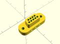
Connector Body
-
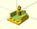
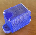
Connector Casing Top
-
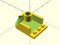
Connector Casing Bottom
-
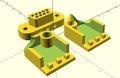
Connector Pieces


Final Prints[edit | edit source]
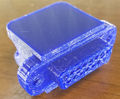
-
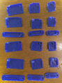
DB Printed Components
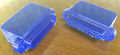
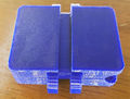
-
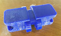
DB Mated Parts
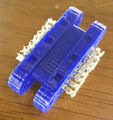
-
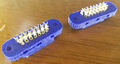
Connector Bodies with Pins
-
DB15 Case Back
-
DB15 Male Connector
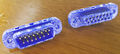
-
DB15 Mated Connectors
-
DB15 with Pins and Sockets
-
DB25 Connectors
-
DB25 Mated Connectors


