
Construction of a laser trip-wire to shut off a Delta printer (specifically MOST delta RepRap) in the event of a detached hotend nozzle or rod which may happen as a result of:
- Printing too fast
- Un-level print bed
- Hotend nozzel impact with a print
ATENTION: You cannot use this method if you have taken up the BTemp digital pin on the Melzi board. This will not be an issue unless you have installed a heated print bed)
This design requires the newest version of the Franklin firmware (as of Dec. 9, 2015).
-
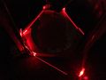
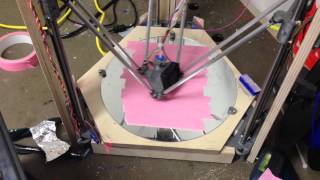
Laser trip-wire (in the dark)
-
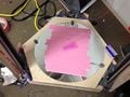
Laser trip-wire (in the light)

Materials Needed[edit | edit source]
- Newest version of Franklin firmware (as of Dec. 9, 2015) Franklin firmware
- A laser light source: I used a BOSCH GTL2 laser level
- A photo resistor: 5mm GL5549 Photo Light Sensitive Resistor CDS
- 4 mirrors measuring 25mm wide by 44mm high, or other reflective surface (I used cut CD's)
- wires
- solder / soldering iron
- heat shrink tubing
- Drill with 3/16 bit
Items to 3D Print[edit | edit source]
- 4 Mirror Mounts *Mirror Mounts
- Photo resistor housing *Photo Resistor Housing
Instructions[edit | edit source]
Upgrade your Delta RepRap printer with the current version of the Franklin firmware (see MOST delta RepRap for details Franklin install). 3D print all needed parts.
Drill holes for mirror mounts.
There is extra outcrops of wood of the base boards sticking out from under the edges of the wood for the print surface
Along the top side of one of these outcrops, measure 1/2" inward and 4/10" width from the closest vertical axis of the printer
Do this for 4 consecutive outcrops
See the photo of the Laser trip-wire set-up in the light if you need a reference
Insert a mirror mount into each hole
Cut your mirrored surface to the above mentioned dimensions and place one into each mount
Place your laser light source on a raised platform so that it can hit your first mirror.
Adjust all mirrors accordingly to angle the beam around the print bed (this is much easier to do in the dark).
Once you have aligned the last mirror to where you want the laser light to end at, mark that section on your printer.
Insert the photo resistor into the housing (making sure the leads come out the back two holes.
Solder a wire onto each lead (can cover with heat shrink tubing)
run the wires into the spare digital pin (BTemp) on the Melzi board (cannot use this pin if you have installed a heated print bed).
Attach the photo resistor mount to your 3D printer (I used 3M VHB tape but use whatever works for you)
Power on printer and go to set the following parameters / pins:
Temps: 2
Gpios: 1
Stop: D30 (check valid, uncheck inverted)
Under Temp Settings - Set new temp sensor name (I used Laser Sensor)
Under Gpio - Name = Sensor, Reset state = Input, Power (%) = 100
Sensor pin: D30 (check valid, uncheck inverted)
There should be a new box named Sensor (or whatever name you gave it) above the Feedrate. It should be checked when no light is hitting the resistor, unchecked when light hits it.
When the box is checked the printer will NOT run. If 'inverted' is checked for BOTH D30 pins, then the printer will not run when light is hitting the resistor and will run in the dark. This can be used if you do not want the printer to run with the laser trip-wire.
Save settings and happy printing
Videos[edit | edit source]
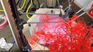
Laser tripped after blocked beam
Laser tripped - thrown rod
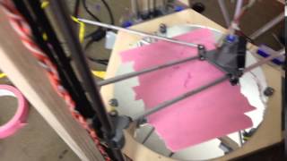
Testing stability of lasers and mirrors while 3d printing]
Notes, Known issues and possible fixes[edit | edit source]
- The printer will only run if the resistance drops below 2.2Ohms. Can monitor this under the temp control window but the values will be read as degrees Celsius (does not matter as long as the value drops below 2.2- or above 2.2 if the pins are inverted)
- Using CD's to reflect the laser light causes much of the energy to be lost around the print bed (due to scattering), hence the need to use a stronger laser source (laser level) - This may be overcome with actual mirrors but was not tested.
- Not all the the edges of the print area were covered by the laser due to having a large laser source off to the side of the print bed and loss of energy not allowing a 5th mirror - could be fixed with a smaller high powered laser, or a smaller laser source with better reflecting mirrors.