Original file (1,104 × 930 pixels, file size: 88 KB, MIME type: image/png)
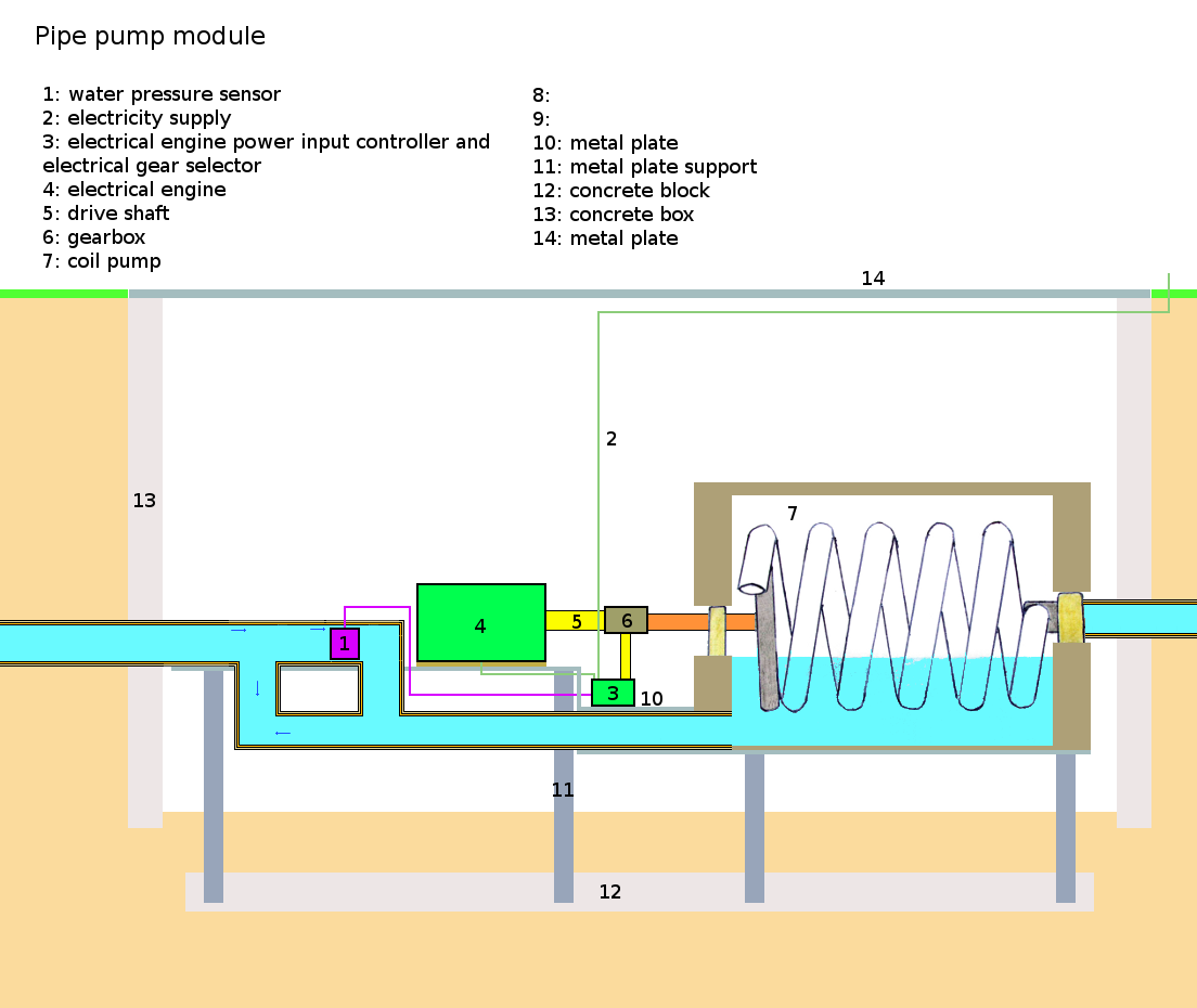
A schematic of a pipe pump module, designed by user:KVDP. The pump shown here is a coil pump. See http://en.wikipedia.org/wiki/File:Coil_pump.jpg
Note that the setup as shown here is intented to work as a pressure sensitive pump, allowing not just switching the pump on/off if the water pressure drops, but also allows the maintaining of a precise water pressure (generally about 4-5 bar). The maintaining of a water pressure is possible, but only if the pump is arranged so so that the head of the pipe is rotated into the water of the tank when not in use. Note that the water inlet would need to be done from the side, and the head of this pipe too must be rotatable (powered by stepper motor); the pipe of the coil pump itself, and water inlet pipe can then rotate exactly towards each other so that, when the pump is not working the water flow is not reduced by the water tank itself.
The workings of the pressure sensitive system is more or less the same as the system in File:EE powered locomotive.png. In essence, 3 is used to regulate the amount of power relayed to the electric engine, based on the sensor data from 1. 3 then determines the input power that needs to be given to the electric engine. In addition, it determines whether or not to increase (or decrease) the gear by 1, when a certain treshold (engine rotation speed, sensor data determining whether to decrease/increase power output) is passed. This is done electromechanically due to the gear selector, which controls the gearbox. Note that in case the pipe needs to be disassembled for repair, it can be lifted out of the concrete pipe/box using a crane, attached around the metal plate (supports are not fixed to it). Also note that a rubber mat is placed between the plate and the engine, to reduce any shocks from the vibrating of the shaft. Also note that the pump module could be used in accordance with the low-cost water transport system Finally, note that 1, the extra pipe section for 1, 3, and 6 could be discarded in case no water pressure sensitive pump is needed (ie for pumps located in pipe sections still far away from the destination point). 2 is then inmediatelly connected to 4, and the pump continuously operates at full power.
File history
Click on a date/time to view the file as it appeared at that time.
| Date/Time | Thumbnail | Dimensions | User | Comment | |
|---|---|---|---|---|---|
| current | 14:59, 13 April 2011 | | 1,104 × 930 (88 KB) | KVDP (talk | contribs) | Changed Francis turbine by coil pump |
| 11:19, 5 April 2011 | 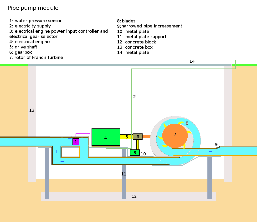 | 1,078 × 930 (50 KB) | KVDP (talk | contribs) | Changed piston pump with Francis turbine. | |
| 14:03, 26 May 2010 | 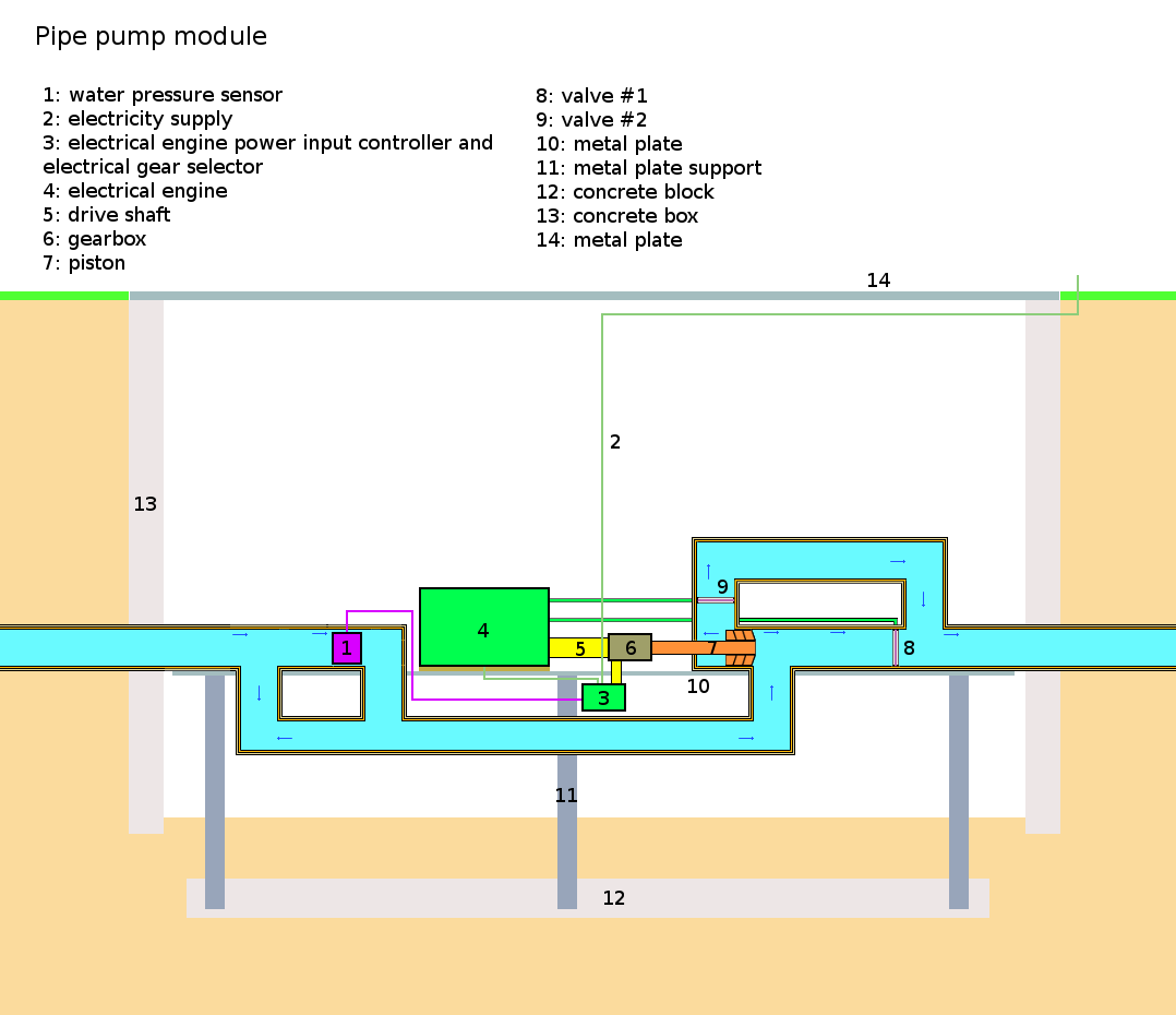 | 1,078 × 930 (38 KB) | KVDP (talk | contribs) | Various | |
| 17:07, 25 May 2010 | 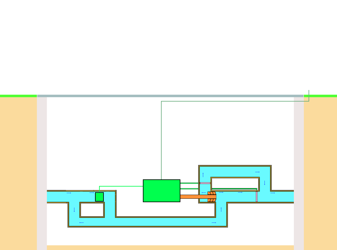 | 1,078 × 800 (9 KB) | KVDP (talk | contribs) | first draft |
You cannot overwrite this file.
File usage
There are no pages that use this file.