Oxyfuel_CCS_fossil_fuel_power_plant_operation.png (466 × 302 pixels, file size: 17 KB, MIME type: image/png)
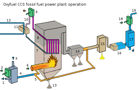
A schematic showing the operation of a oxyfuel carbon capture and storage (CCS) fossil fuel power plant. The schematic was based on the image at http://news.bbc.co.uk/2/hi/science/nature/7586569.stm , and the information in EOS magazine, March 2010.
1= air inlet
2= mechanical energy is supplied
3= nitrogen outlet
4= oxygen outlet
5= recycled exhaust gas inlet
6= fuel inlet (ie coal, ...)
7= cold water pipe
8= steam inlet pipe
9= steam turbine
10= steam outlet pipe
11= steam condensor
12= cooling pipe of steam condensor
13= bottom ash
14= fly-ash removal
15= sulpher + gypsum removal
16= cooler
17= water condensor (water removal)
18= mechanical energy is supplied (CO²-compressor)
19= CO² outlet
Note 1: 6, 7 and 8 form the whole of the firebox < br/>
Note 2: for the workings of the steam condensor (a non essential part, simply increases efficiency), see http://commons.wikimedia.org/wiki/File:Surface_Condenser.png < br/>
File history
Click on a date/time to view the file as it appeared at that time.
| Date/Time | Thumbnail | Dimensions | User | Comment | |
|---|---|---|---|---|---|
| current | 18:37, 2 July 2010 | | 466 × 302 (17 KB) | KVDP (talk | contribs) | Got confused with new part: the steam condensor; changed image, now correct |
| 15:38, 28 May 2010 | 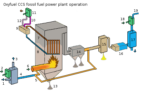 | 466 × 302 (17 KB) | KVDP (talk | contribs) | A schematic showing the operation of a oxyfuel carbon capture and storage (CCS) fossil fuel power plant. The schematic was based on the image at http://news.bbc.co.uk/2/hi/science/nature/7586569.stm , and the information in EOS magazine, March 2010. 1= ai |
You cannot overwrite this file.
File usage
The following file is a duplicate of this file (more details):
- File:Oxyfuel CCS fossil fuel power plant operation.png from Wikimedia Commons
The following page uses this file: