No higher resolution available.
Figure2.png (276 × 214 pixels, file size: 7 KB, MIME type: image/png)
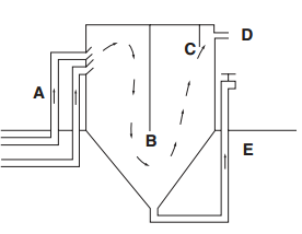
Figure 2. A descriptive picture of a clarifier. First water and sludge enter B) the central baffle then move either to E) the sludge drain or D) the outlet to the filter tanks. C) is the discharge baffle.
File history
Click on a date/time to view the file as it appeared at that time.
| Date/Time | Thumbnail | Dimensions | User | Comment | |
|---|---|---|---|---|---|
| current | 01:22, 16 December 2012 | | 276 × 214 (7 KB) | Kmnachbo (talk | contribs) | Figure 2. A descriptive picture of a clarifier. First water and sludge enter B) the central baffle then move either to E) the sludge drain or D) the outlet to the filter tanks. C) is the discharge baffle. |
You cannot overwrite this file.
File usage
The following page uses this file: