
File:EE powered locomotive.png
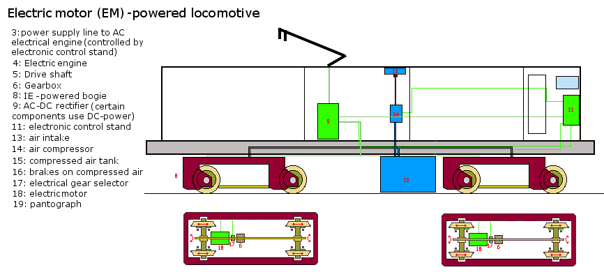
A schematic of a electrical motor (or electrical engine; EE) powered locomotive. The schematic was based on the images at http://web.archive.org/web/20161215020629/http://www.railway-technical.com/diesel.shtml; the bogie brakes were made based on the image at http://web.archive.org/web/20170318131006/http://railway-technical.com:80/bogie1.shtml, and information at http://en.wikipedia.org/wiki/Railway_air_brake . Note that 3 compartments were made in the image, to clearify schematic, increase safety & facilitate repair, ... The electronic control stand is used also to regulate the amount of power relayed to the electric engines in the bogies (from the pantograph), based on the how far the gas throttle is pushed in by the driver. Inside the electrical engine, a sensor is placed taking notice of this power amount. The electronic control stand could possibly be made on a "open design" manner; this will decrease the cost of production for a wide range of railway vehicles, and integrate more uniformity between the vehicles.
File history
Click on a date/time to view the file as it appeared at that time.
| Date/Time | Thumbnail | Dimensions | User | Comment | |
|---|---|---|---|---|---|
| current | 08:19, 20 February 2013 | | 866 × 390 (35 KB) | KVDP (talk | contribs) | removed a wheel per bogey |
| revert | 13:34, 8 February 2013 | 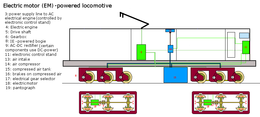 | 866 × 390 (35 KB) | KVDP (talk | contribs) | |
| revert | 12:49, 8 February 2013 |  | 866 × 390 (35 KB) | KVDP (talk | contribs) | used integrated motor bogeys for this aswell, hereby increasing traction |
| revert | 14:23, 7 May 2010 | 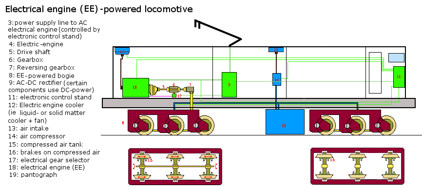 | 866 × 390 (43 KB) | KVDP (talk | contribs) | A schematic of a electrical engine (EE) powered locomotive. The schematic was based on the images at http://www.railway-technical.com/diesel.shtml; the bogie brakes were made based on the image at http://www.railway-technical.com/bogie1.shtml, and informa |
You cannot overwrite this file.
File usage
There are no pages that use this file.