The Athena uses a j-head hot end with a 0.5mm nozzle and accepting 1.75mm filament. There are different versions of the j-head - the one discussed here has the PEEK insulator and is designed for PLA and ABS filament. Even this design has a couple variants, one using a radial lead thermistor (bead-type) and another using an axial lead thermistor. The axial lead thermistor version is recommended as the thermistor leads are much more robust as compared to the brittle, hair-thin leads of the radial lead version. Regardless of the design variant, assembly is essentially identical. These instructions assume the axial lead thermistor is used.
Test the fit of the resistor in the heating block.In some cases, the ceramic coating of the resistor is too large for the hole in the heating block. Press the resistor into the hole. Do not be concerned if some of the ceramic chips off. Remove the resistor from the hole.
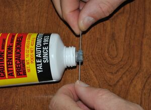
Smear muffler cement on heating resistor.Strike off cement and pack around resistor.Smear a small amount of muffler cement around the entire exterior of the heating resistor and insert it into the large hole in the hot end's brass heating block. With the stick, strike off and pack cement in the ends. Set the hot end aside and let the muffler cement cure for several hours (24 hours recommended).
Push the larger PTFE insulation onto the resistor leads. Push the larger PTFE insulation cut to 19mm length onto the leads of the resistor. Push the insulation all the way to the resistor body. If necessary, carefully clean off cured muffler cement from the leads with the precision knife.
Trim the resistor leads leaving 6mm exposed.Leave 6mm of the resistor leads exposed. Trim the resistor leads with wire cutters, leaving 6mm of the leads exposed for later soldering.
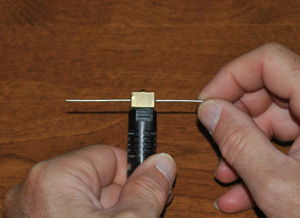
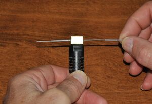
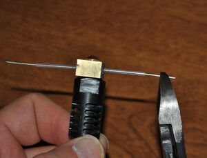
Insert thermistor.Insert the thermistor and push the 25mm long PTFE insulators onto the leads. Approximately 4mm of the thermistors leads should be exposed for later soldering. Slide the thermistor into the small hole in the hot end's brass heating block.
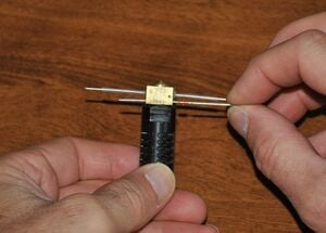
Bend the resistor and thermistor leads towards top of hot end.Taking care to not dislodge the resistor, bend its leads up towards the top of the hot end. Do similarly with the thermistor leads, keeping the thermistor centered in the heating block.
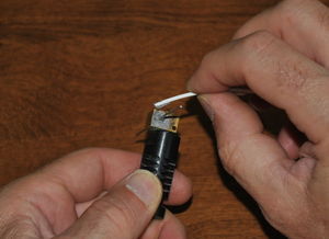
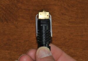
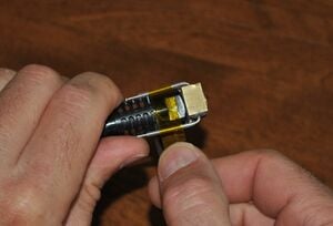
Kapton tape securing leads to hot end.Insure that the PTFE insulation is pushed fully onto the leads and 6mm of the resistor leads are exposed and 4mm of the thermistor leads are exposed. Wrap kapton tape around the leads at the base of the plastic heatsink so that none of the openings in the heatsink are covered. Make 3-4 tight turns with the kapton tape, firmly securing the leads to the side of the hot end. This will relieve straining of the leads, improving performance and life of the hot end.